


Electro Industries/GaugeTech
Doc # E107706 V1.25 1-2
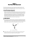
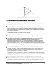
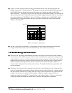
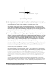
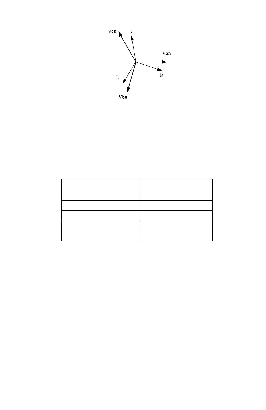
Fig 1.2: Phasor Diagram Showing Three-phase Voltages and Currents
Q
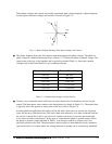
The phasor diagram shows the 120
o
angular separation between the phase voltages. The phase-to-
phase voltage in a balanced three-phase wye system is 1.732 times the phase-to-neutral voltage. The
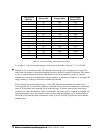
center point of the wye is tied together and is typically grounded. Table 1.1 shows the common
voltages used in the United States for wye-connected systems.
Table 1.1: Common Phase Voltages on Wye Services
Q
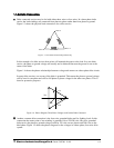
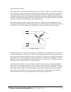
Usually a wye-connected service will have four wires; three wires for the phases and one for the
neutral. The three-phase wires connect to the three phases (as shown in Figure 1.1). The neutral wire
is typically tied to the ground or center point of the wye (refer to Figure 1.1).
In many industrial applications the facility will be fed with a four-wire wye service but only three
wires will be run to individual loads. The load is then often referred to as a delta-connected load but
the service to the facility is still a wye service; it contains four wires if you trace the circuit back
to its source (usually a transformer). In this type of connection the phase to ground voltage will be
the phase-to-ground voltage indicated in Table 1, even though a neutral or ground wire is not
physically present at the load. The transformer is the best place to determine the circuit connection
type because this is a location where the voltage reference to ground can be conclusively identified.
Three-phase voltages and currents are usually represented with a phasor diagram. A phasor diagram
for the typical connected voltages and currents is shown in Figure 1.2.
Phase-to-Ground Voltage Phase-to-Phase Voltage
120 volts
277 volts
2,400 volts
7,200 volts
208 volts
480 volts
4,160 volts
12,470 volts
7,620 volts 13,200 volts