


––++G
A(+) B(-) S - V + A(+) B(-) S - V +
+V- SB(-)A(+)
+V- SB(-)A(+) +V- SB(-)A(+)
+V- SB(-)A(+)
87654321C -+
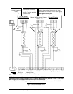
Port 1
RS-232 or
RS-485 (Set)
RS-232
RS-485
Port 2
Normally Slave
Modem/Ethernet Gateway
High Speed Inputs
IRIG-B
RS-485 Master
Unicom or Modem Manager
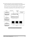
Nexus P40N External Display
Nexus I/O Module
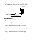
RS-232 Extension
Cable
(1 to 1 wiring)
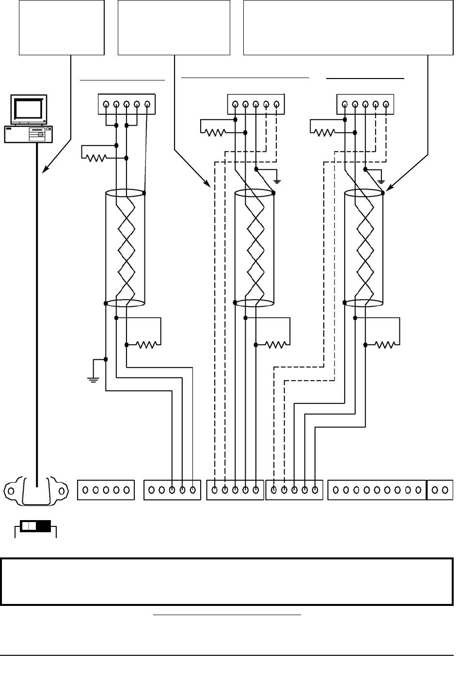
I/O Modules and Display
require power connections
to the +/- voltage terminals
(dashed lines).
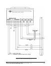
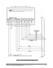
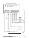
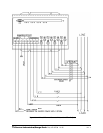
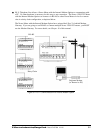
For all communications: S=Shield. This connection is
used to reference the Nexus port to the same
potential as the source. It is not an earth-ground
connection. You must also connect the shield to
earth-ground at one point.
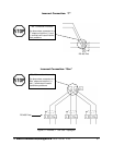
R
T=
~120 Ohms
R
T=
~120 Ohms
R
T=
~120 Ohms
R
T=
~120 Ohms
R
T=
~120 Ohms
R
T=
~120 Ohms
e
Electro Industries/GaugeTech
Doc # E107706 V1.25 5-4
Port 3 Port 4
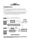
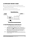
Figure 5.4: Communication Wiring
NOTE: You may use ANY port to connect a Nexus Display or RS-485 Master. However, if you are using
the Internal Modem (or Network) Option, Port 2 is labeled Modem (Ethernet) Gateway. Ports 1, 3 and 4 DO
NOT change. The I/O Modules MUST use Port 4 (Port 3 is an alternate).
Nexus P40N, P41N or P43N Display is shipped programmed to use Port 3—see section 5.7 for
details.