


2-14 IntelliTouch/SecureTouch Guide
• Various cables connected to the power switch, pilot light, front panel
controls, etc.
Other cables may have to be unplugged from the electronic chassis. The need
for this may not be apparent until the chassis is removed, as instructed below.
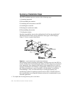
Another preliminary step in determining touchscreen/display compatibility
should be performed at this point. Before removing the electronics chassis, note
the clearance between the chassis components and the bell of the CRT. Since
the standard technique for mounting the touchscreen involves moving the CRT
back in the display chassis, there must be enough clearance between
components on the chassis and the CRT after allowing for about 0.25-inch
(6 mm) movement of the CRT towards the rear of the chassis. Failure to allow
for this clearance requirement may result in mechanical damage later
(especially in shipping). It may also cause electrical damage from shorts
between “live” components on the chassis, such as heat sinks or uninsulated
component leads, and the bell of the CRT which is usually painted with a
conductive coating that is grounded to the chassis through the braided wire
ground strap. Repositioning or substituting low profile components may be an
option. Contact Elo Technical Support, (1-800-557-1458 x6), for assistance.
After disconnecting any necessary cables remove the screws that attach the
electronics chassis to the bezel. Note the bezel is essentially where all parts of
the mechanical assembly are attached, unless you have a rare unit that has an
internal frame. As you pull the chassis away from the bezel, make sure that
cables and circuit boards do not hit the neck of the CRT and that nothing
becomes caught on the adjustment rings or other components on the neck of the
CRT. Also watch for other cables that need to be disconnected. After removal,
set the electronics chassis aside.