2-26 IntelliTouch/SecureTouch Guide
CAUTION
Observe polarity when connecting the power leads to the power supply. Reversing
polarity may damage the controller.
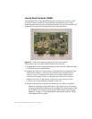
Possible power supply sources included:
• A direct power cable to a +5 Vdc source inside the display or tap unregulated
monitor power in the +9 Vdc to +30 Vdc range using the Elo DC-to-DC
converter (See “Elo Part Numbers” on page 79). Attach the direct power
cable (See “Elo Part Numbers” on page 79) to the source, red to + 5 Vdc and
black to common. You must attach the green ground cable to a suitable
chassis ground for noise immunity and safety considerations. Observe
polarity when connecting the power leads to the power supply. Reversing
polarity will damage the controller.
• Typical converter power consumption is approximately 1 W. Remember
that each integration situation is unique; you must carefully evaluate
available power rails and consider how drawing additional power from the
display will affect monitor performance.
• Install a power supply which requires a 100-240 Vac input. Connect a power
cable harness to P4 on the controller, a 2x5 header with pins on 0.100-inch
(2.54 mm) centers. Use a ribbon cable with an IDC connector or crimp-to-
wire pin receptacles. An acceptable plug can be selected from Molex series
70450, Amp AMPMODU Mod. IV product line, or Berg mini-latch housing
with Mini-PV pins. Connect a power supply to the harness and then to AC.
• If none of the above options are practical, you must use either an optional
keyboard power tap or wall-mount power supply to furnish +5 Vdc power
to the controller.
CAUTION
Before using a keyboard power tap, be sure sufficient power is available for the
touchscreen controller or damage may occur to the computer.
Before connecting a keyboard power tap to the controller, be sure that power to the CPU
is OFF. Connecting a keyboard power tap to a powered CPU may seriously damage the
CPU or the controller and will blow the keyboard fuse.
1 Decide where to mount the controller on the rear of the display case. After
choosing a location, use masking tape to hold the template in the desired spot
and drill a 1-inch diameter hole for cabling exiting the display and drill two
holes for screws that will be mounted in the display case.
2 Route the touchscreen cable (and power cable if using an internally located
power source) through the 1-inch diameter hole in the display case. Insert the
touchscreen cable into the keyed receptacle in the rear of the controller box.
You will hear a “click” when the cable connector is properly connected to the
controller. Pull any excess cabling back into the display case and attach the
controller to the display case.
3 Wrap excess cabling with tie wraps as required, and proceed to “Routing the
Touchscreen Cables” on page 2-29.


