


B-75
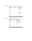
Table B.7
Power connector, P4, pins and signal names
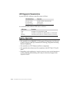
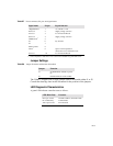
Jumper Settings
Table B.8
Jumper Locations and function if installed
The 2500S is shipped with a single jumper fitted to not enable either J1 or J2.
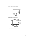
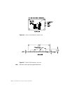
Consult the drawings later in this document for the position of the jumpers.
LED Diagnostic Characteristics
A green LED indicates controller status as follows:
Signal name P4 pin Signal function
+Regulated Pwr 1 +5 volts DC +/- 5%
Pwr Com 2 Supply voltage common
reserved 3 no connection allowed
Pwr Com 4 Supply voltage common
LED Remote
1
1. Source impedance is 500 ohms to Vcc. Current drive available for typical LED is 6mA.
5
n/c 6 key location
n/c 7
Frame ground 8
-Reset 9 Open = normal operation
short to Pwr com = hardware reset.
reserved 10 no connection allowed
Jumper Function
J1 Set NVRAM to defaults on power
up
J2 Emulation Mode = E281A-4002
LED Blink Rate Function
Once per second Normal condition, untouched state
On continuously Touched state
Twice per second Error detected