


2-22 IntelliTouch/SecureTouch Guide
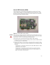
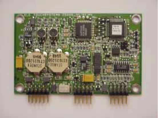
Internal Serial Controller (2500S)
The mounting holes of the IntelliTouch serial controllers are sized for 0.156-
inch (4mm) snap-in standoffs. All IntelliTouch touchscreens have a cable
termination that mates directly with the male header (P3) on the controller. See
Appendix B for specific mounting dimensions and connections.
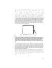
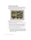
Figure 2.5
Touchscreen Cabling System for Internal Serial Controller
Follow these steps to install an IntelliTouch serial controller:
1 Evaluate the monitor for proper positioning of the controller. Make sure there
is sufficient space for cable headers.
2 Evaluate the back case of the monitor to determine the best position for the
DB9 female connector. A hole for this connector may be furnished in a
variety of ways: a) mounting the connector to a chassis member that is
exposed to the display exterior, b) mounting the connector to a chassis
member with a hole in the exterior of the case to provide access to the
connector, and c) mounting the connector to the case.
3 Mount and ground the controller card following one of the two methods:
• Mount the controller to the metal chassis using metal screws and spacers.
It can be grounded through one of the mounting holes by using one of the
No. 6 sheet metal screws and spacers provided in the kit (See “Elo Part
Numbers” on page C-79 for installation kit part number). On the 2500S,
all mounting holes are plated.