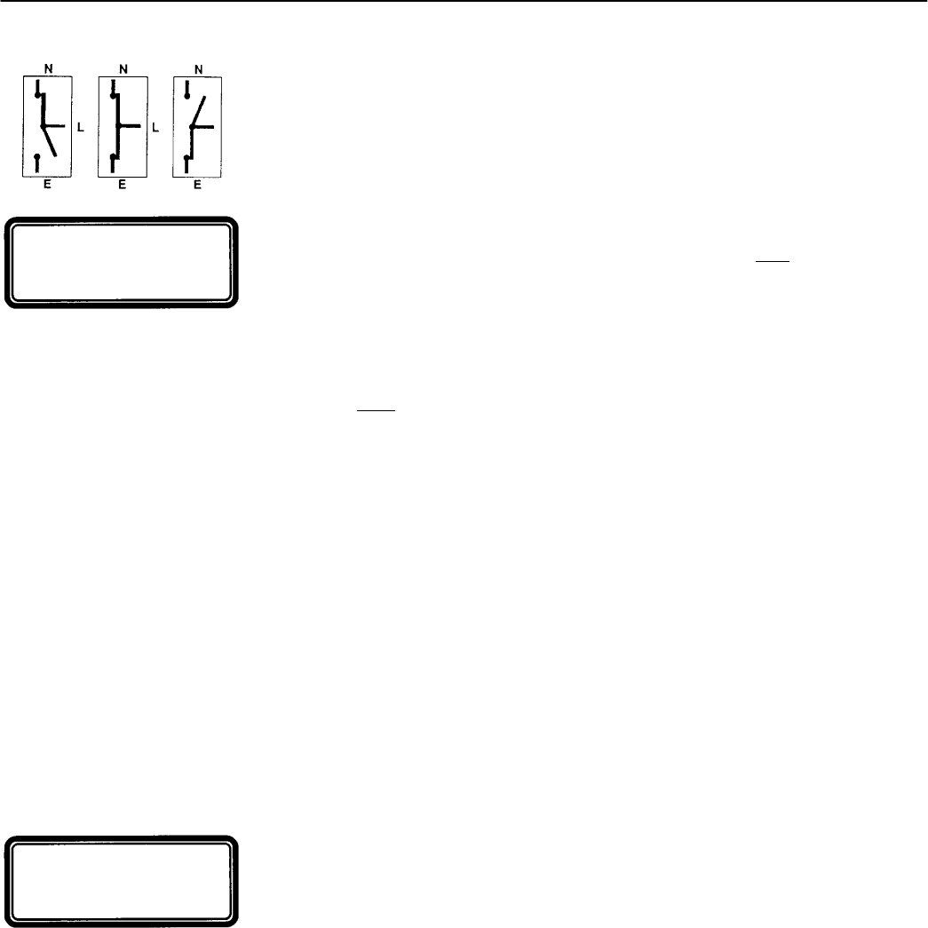
4--4 Description of Operation
Closed–Transition Automatic Transfer Switches continued
Closed–Transition Load Transfer to Emergency Source
due to Transfer Test
The sequence for closed–transition load transfer to the emergency source begins
automatically when the controller detects a transfer test signal.
Transfer Test Signal. Test transfer signal can be from the Tr an sfe r Contr ol switch
(Feature 5), the engine–generator exerciser clock (Feature 11C), or via the serial port
(Feature 72A). When using the Tr an sfe r Con tro l switch,itmustbeheld
in the TransferTest
position until the emergency source becomes available (within 15 seconds).
The controller begins the load transfer sequence by de–energizing the SE, SE2, and NR
relays. Feature 1C engine starting time delay is bypassed during transfer test.
Engine Start Signal. When the NR relay de–energizes it signals the engine–generator
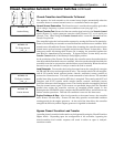
to start. The controller monitors the emergency source, waiting for it to become
acceptable. Both
voltage and frequency must reach preset pickup points before the
emergency source is accepted. Usually about 10 seconds elapse from dropout of the NR
relay to acceptance of the emergency source. This interval occurs because the
engine–generator must crank, start, and run up to nominalpickup points.If the emergency
source is available immediately, the controller will accept it as soon as the NR relay drops
out.
When the emergency source becomes acceptable, the controller starts the F eature 2B time
delay on transfer to emergency (if desired). If the emergency source fails while Feature 2B
time delay is running, the controller again waits for the emergency source to become
acceptable again and restarts Feature 2B.
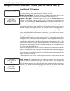
At the conclusion of the Feature 2B time delay, the controller starts the synchronization
time delay which allows both sources to stabilize. After the synchronization time delay,
the controller starts the in–sync monitor. Three criteria must be met for the sources to be
considered in–sync. The phase difference between the sources must be lessthan 5 degrees,
thefrequencydifferencemustbelessthan0.2Hz,andthevoltagedifferencemustbeless
than 5%. These parameters are displayed. The controller waits for the sources to become
in–sync. At the same time, the failure to sync time delay is running. If the failure to sync
time exceeds the user selected ti me, the failure to sync output is activated and remains
active until it is reset via the alarm reset. The controller continues the transfer sequence
even after the fai lure to synchronize alarm becomes active.
Whenthe sourcesbecome in–sync the controller is ready to transfer the load to emergency.
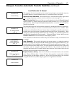
Load Transfer. To transfer the load to the emergency source the controller energizes the
ER2 relay. The transfer switch CE coil energizes, and all CE transfer switch contacts
(mains, controls, auxiliaries) reverse position. The load is connected to both the Normal
and Emergency sources. The extended parallel time delay is started and the controller
energizes the ER relay. The transfer switch CN coil energizes, and all CN transfer switch
contacts (mains, control, auxiliaries) reverse position to disconnect the Normal source.
The load is now only connected to the Emergency source. If the sources are paralleled
longer than the extended parallel time setting the controller activates an extended parallel
output. It also deenergizes the ER and ER2 relays, energizes the SE and SE2 relays, and
it locks out any further transfer operations. This lock–out condition is reset via the alarm
reset.
TEST MODE
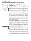
TEST CIRCUIT 5
Waiting for Emerg
Acceptable
TEST MODE
TEST CIRCUIT 5
Load on Emerg


