A --- 2Appendix
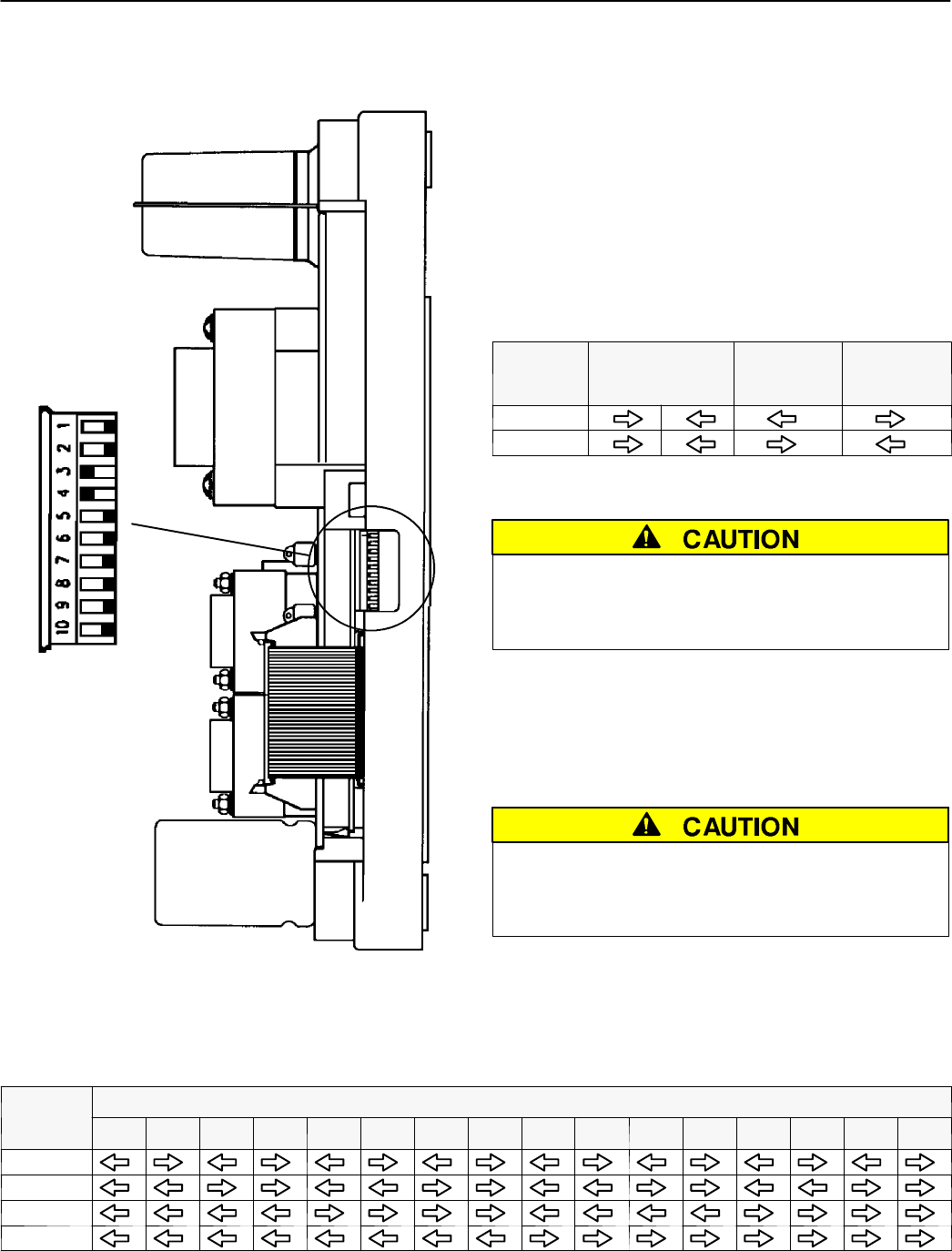
DIP Switch Actuators
DIP switch
(10 actuators)
right side of
controller
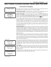
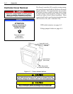
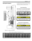
The DIP switch in the Group 5 controller is located on
the right side through a opening in the base. The
following tables show what each actuator does.
Transfer Switch Type
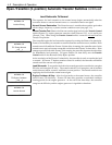
DIP switch actuators 1 and 2 select the type of transfer
switch used with the controller (open–transition,
closed–transition, or delayed–transition). See Table A.
TableA. Transferswitchtype—DIPactuators1&2.
DIP
switch
actuator
open
transition
or *
closed
transition
delayed-
transition
1
2
* For open–transition, both actuators 1 & 2 must be
in the same position (either both right or both left).
To avoid permanently damaging the Group 5
controller and/or disabling it, be certain that the
setting matches the transfer s witch type.
Nominal Source Voltage Selection
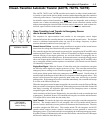
DIP switch actuators 3, 4, 5, and 6 select the input volt-
age to the controller. See Table B.
To avoid permanently damaging to the Group 5
controller, be certain that the voltage setting
matches the transfer switch sy stem voltag e.
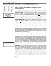
Figure A–2. Location of DIP switch.
Table B. Nominal Input Voltage — DIP actuators 3, 4, 5, & 6.
DIP
s
w
i
t
c
h
Input Voltage to Controller
sw
i
t
c
h
actuator
115 120 208 220 230 240 277 380 400 415 440 460 480 550 575 600
3
4
5
6


