A --- 4Appendix
Voltage Jumper Blocks
To avoid permanently damaging the Group 5
controller, be certain that the voltage setting
matches the transfer switch system voltag e.
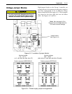
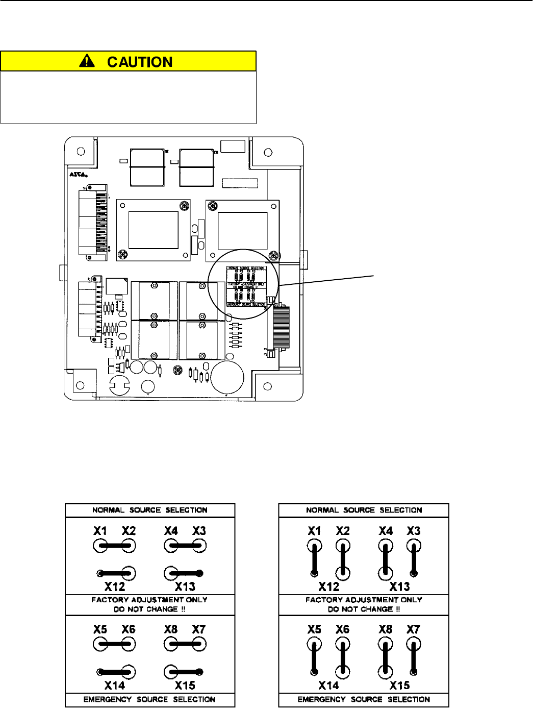
Eight jumper blocks on the Group 5 controller are
arranged in one of two patterns for the power supply to
meet the requirements of the 16 different voltage
inputs (shown in Table B on page A–2). These jumpers
are located on the front right side near the ribbon
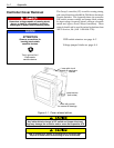
cable. See Figures A–3 and A–4.
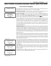
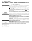
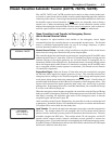
jumper blocks
(see Figure A–4)
Note: Also see page A–2 for
Nominal S ource Voltage Selection
DIP switch actuator settings.
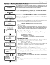
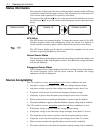
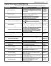
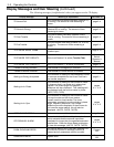
Figure A–3. Location of jumper blocks.
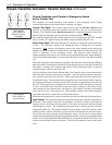
Nominal v oltage Nominal v oltage
115 — 277 V 380 — 600 V
(115, 120, 208, 220, 230, 240, 277) (380, 400, 415, 440, 460, 480, 550, 575, 600)
P osition jumpers HORIZONT ALLY P osition jumpers VERTICALLY
Figure A–4. Power supply jumper arrangements.


