10
Safety Information Product Overview Installation Diagnostics
Options and
Accessories
Specification
Step 3: High Power Connections
System Grounding
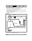
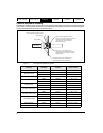
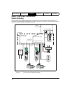
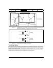
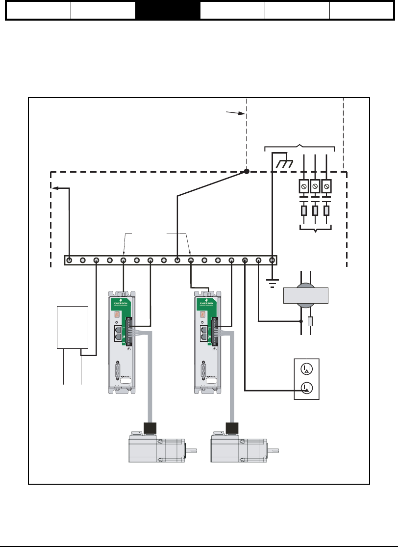
To insure a safe and quiet electrical installation, good system grounding is imperative. The figure below is an
overview of the recommended system grounding. For more information on achieving an electrically quiet installation
refer to “Step 1: Basic Installation Guidelines” on page 3.
Figure 6: Typical System Grounding Diagram
PE
Connection
PE
Connection
Epsilon
Drive
Epsilon
Drive
Single Point Ground
(Bonded to Enclosure)
Motor Motor
Convenience
Outlet
3 Phase
Line Power
Control
Transformer
Output
Neutral Hot
Fuses
Conduit or
Metal
Raceway
Enclosure
AC Power Supply
Redundant PE
Connection
To Enclosure Door
Door Bond Wire
Conduit Raceway Bond
Logic
Power
Supply
24 Vdc
+ -
Epsilon EP
reset
3 MIN
serial (J2)
L1
L2
PE
S
R
T
+
_
logic motor
digital i/o (J3)
J8
J6
J5
J10
EP204-I00-0000
9606XX-XX A1
SN 0610E014
Epsilon EP
reset
3 MIN
serial (J2)
L1
L2
PE
S
R
T
+
_
logic motor
digital i/o (J3)
J8
J6
J5
J10
EP204-I00-0000
9606XX-XX A1
SN 0610E014


