36
Safety Information Product Overview Installation Diagnostics
Options and
Accessories
Specification
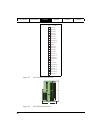
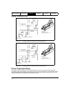
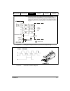
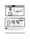
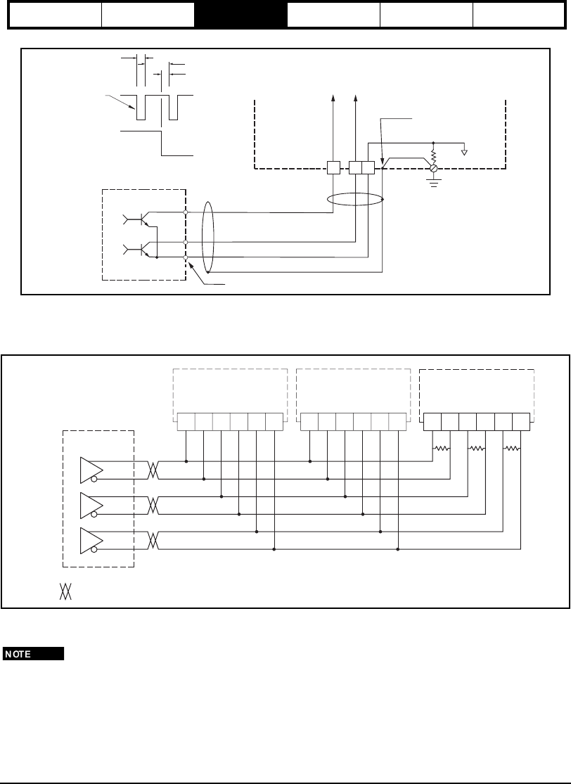
Figure 41: Pulse/Pulse Mode, Single Ended Output to Single Ended Input (non-twisted
pair cable)
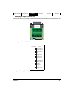
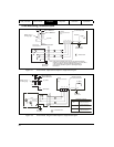
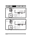
Figure 42: Master/Slave Encoder Connections
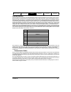
Encoder outputs meet RS-422 driver specifications and can drive up to 10 RS-422 signal receivers. Each
differential pulse input is an RS-422 line receivers. The default encoder output resolution is 2048 lines per
motor revolution. This resolution is adjustable in one line per revolution increments with PowerTools Pro
software. The range is between 1 and the actual motor encoder density.
Common isolated from other sources
Sinking
Outputs (typ)
logic
common
PE
10
Ohm
Drive
Analog/Sync Output Connector
(J5)
CCW Pulse
CCW Pulse
Single Point
Panel Ground
CW
CCW
CW Pulse
1 µs Minimum
500 ns Minimum
1 µs Minimum
Motion occurs
on falling edge
CW Pulse
Shield connected
to connector shell
8
12
4
Pulse
Direction
R1 R2 R3
Sync Input Connector (J10)
A A/ B B/ Z Z/
1 2 3 5 6 7
Sync Input Connector (J10)
A A/ B B/ Z Z/
1 2 3 5 6 7
Slave Drive
Slave Drive
Slave Drive
A A/ B B/ Z Z/
1 2 3 5 6 7
Sync Input Connector (J10)
R1, R2, and R3 must be mounted within 3 ft [1m] of the end drive.
A 120 ohm resistor is recommended for high frequency
(over 250 kHz) stepping or cable lengths longer than 25 feet.
Note:
= Twisted Pair
RS-422
Drivers
Master Encoder
or Drive Output


