Diagnostics and Troubleshooting 47
Safety Information Product Overview Installation Diagnostics
Options and
Accessories
Specification
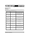
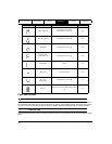
Trajectory Fault #2
This fault occurs when using the "Using Capture.#" option in a user program. If the capture has never been triggered,
or the capture data has gone "stale", the drive will not be able to process motion properly.
Program Fault
This fault indicates a problem was encountered in a user program. For example: an illegal math operation resulting
in a divide by zero or overflow of 32-bit data. This error can also occur if trying to access a drive parameter that is
non-existent or not available to the user.
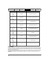
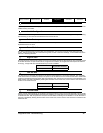
Invalid Configuration Fault #2
The user program in flash memory will not run. Download the user program again using PowerTools Pro. A common
cause of this fault could be an interrupted configuration download, such as a cable being disconnected during the
download.
No Program
This fault will be displayed on initial power-up indicating that no configuration has been downloaded to the drive. To
clear the fault, download a valid configuration to the drive.
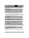
All "On"
This is a normal condition during power up of the drive. It will last for less than 1 second. If this display persists, call
Control Techniques Americas LLC for service advice.
Normally, "All On" for less than one second during power-up. All segments dimly lit when power is "Off" may occur
when an external signal is applied to the encoder inputs (motor or master) or serial port from an externally powered
device.
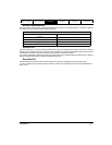
Diagnostic Analog Output Test Points
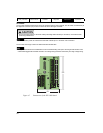
The drive has two 10-bit real-time Analog Outputs which may be used for diagnostics, monitoring or control
purposes. These outputs are referred to as Channel 1 and Channel 2. They can be accessed from the Analog/Sync
Output Connector (J5) on the drive.
Each Channel provides a programmable Analog Output Source.
Analog Output Source options are:
• Velocity Command
• Velocity Feedback
• Torque Command (equates to Torque Command Actual parameter)
• Torque Feedback
• Following Error
• Position Feedback (EP-B, EP-I, and EP-IDN)
• Custom Variable (EP-P only)
• Analog In (EP-P only)
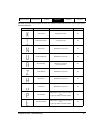
Drive Faults
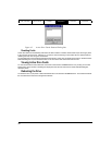
The Active Drive Faults dialog box is automatically displayed whenever a fault occurs. There are two options in this
dialog box: Reset Faults and Ignore Faults.
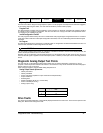
Channel
Analog/Sync Output Connector (J5)
Pin#
17
215


