18
Safety Information Product Overview Installation Diagnostics
Options and
Accessories
Specification
Both supply conductors must be fused except one that is grounded. The fuse must be rated for at least the voltage
applied. The current rating of the fuse should match the rated output current of the drive. A slow-blow fuse should
be used if high peak loads are expected.
External Shunt Electrical Installation
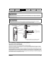
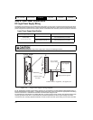
The EP204 and EP206 drives provide an internal shunt transistor to direct regen energy to an external shunt or
braking resistor. The resistor is connected to the B+ and SH terminals at J8 on the top of the drive.
Shunt Control
The shunt transistor turns on when the bus voltage reaches 405 Vdc and shuts off when the bus voltage falls below
390 Vdc. An internal shunt control algorithm is used to prevent the external shunt resistor from overloading. It is
necessary to enter shunt energy rating, power rating and resistance for the attached shunt resistor in PowerTools
Pro software. Energy rating is the amount of energy that the resistor can absorb in a single shunt event assumed to
be so short that power dissipation is negligible. Power rating is the long term average power that can be dissipated.
PowerTools Pro default values are for the Control Techniques "SM-Heatsink DBR-1" resistor kit, marked P/N 1220-
2756-01 on the resistor.
External Shunt Resistor
Control Techniques offers an external shunt resistor kit, SM-Heatsink DBR-1, that attaches directly to the EP drive
heatsink. The resistance is 75 Ohms and has 1500 Joule energy rating and 50 W continuous power rating. It is
adequate for most infrequent machine stop sequences due to relatively high energy rating for its power rating. It
should be suitable for any EP204 application unless average power exceeds 50 W for repetitive cycles. For an
EP206, some applications may require lower resistance to prevent a high bus fault or higher energy rating for a single
event, as well as higher average power rating. The resistor in the kit is designed to eventually open in the event of
a shorted control transistor when operating with an AC input greater than 200 Vac. At this time the kit should be used
only when the drive is operating at 200 Vac to 240 Vac.
A different external shunt resistor should be used if average power is above 50 W, or other limits are exceeded as
described above. Higher power resistors should be mounted away from the drive to prevent overheating. If thermal
loading inside a cabinet is an issue, a resistor with suitable enclosure may be installed external to the drive enclosure.
The minimum resistance for an external shunt resistor is 33 Ohms. The resistor must have thermal overload
protection to remove power in the event of a shorted control transistor. The protection can simply open the circuit, in
which case a high bus fault will occur, or be wired to a contactor that isolates input power from the drive on overtemp.
Shunt Resistor Kit Installation
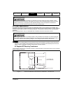
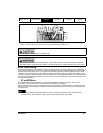
The SM-Heatsink DBR-1 attaches to the side of an EP204 or EP206 drive by lining up the two captive screws to the
special width slots in the heat sink. The exact position along the slot does not matter as long as the body of the
resistor does not extend beyond the top or bottom of the drive. Use a T-20 Torx driver to thread the screws into
position. After both are well started but not tight, carefully turn each screw until it is seated against the resistor and
the resistor back is seated against the heat sink. Then turn the screw 1/8 turn more. Do not overtighten.
Strip 0.12 inch [3.0 mm] insulation from the ends of the resistor wires. Install the wires in the SH and B+ terminals of
J8 and tighten to 5 in-lb. Make sure the locking screws are installed on J8 to prevent the connector from pulling out.
Shunt connections at J8 remain at dangerous Voltages after disconnecting AC Power. Power must be "Off"
for a minimum of 6 minutes for an EP206 and 3 minutes for an EP202/204 before touching these terminals.


