Installation 17
Safety Information Product Overview Installation Diagnostics
Options and
Accessories
Specification
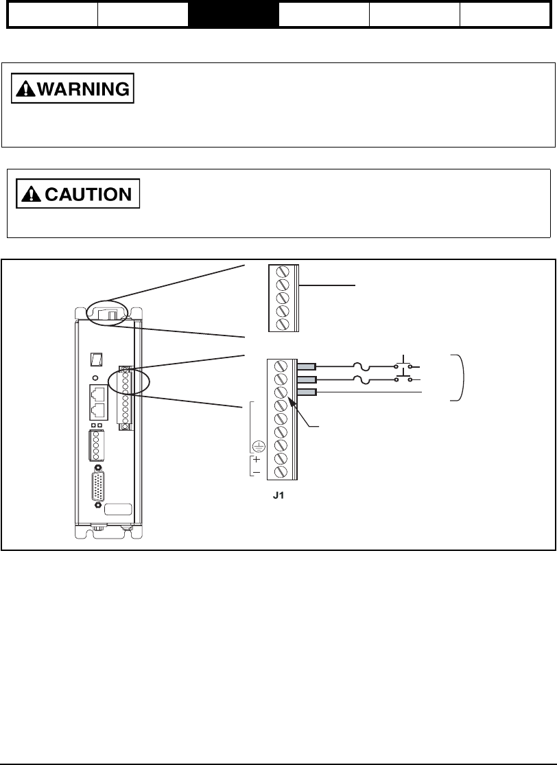
AC Input Power Connections
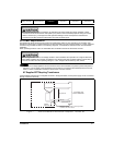
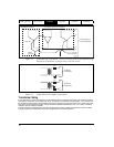
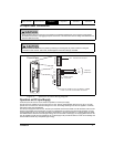
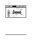
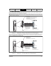
Figure 14: Epsilon EP AC Power Wiring Diagram
Operation on DC Input Supply
At this time, the EP drive is not UL listed for operation on a DC input supply.
The EP drive can operate on DC input as low as 10 Vdc, though recommended minimum is 24 Vdc. It can also
operate from a common DC link with voltage to 373 Vdc, the voltage resulting from 264 Vac applied to a rectifier,
with regen to 400 Vdc intermittently.
For DC input supply less than 24 Vdc, the DC input should be connected to the B+ and B- terminals at J8 to avoid
losses in the rectifier and inrush limiter. At such low voltages the bus caps do not need inrush protection. For DC
supply greater than 24 Vdc, the supply should be connected to L1 and L2 terminals on J1. Polarity does not matter.
The rectifier blocks reverse current so regen energy will not come back to the supply. DC supply greater than 24 Vdc
may be applied to the B+ and B- terminals of J8, but the supply must provide soft-start or inrush current limiting and
must be able to handle any anticipated regen energy.
Power must be "Off" for a minimum of 6 minutes for the Epsilon EP206 drive and 3 minutes for the Epsilon
EP202/204 drives before unplugging the power connection. This will ensure the bus voltage has bled down to a
safe level (below 50 Vdc).
Do not connect or disconnect AC power by inserting or removing the AC power connector. Using the
connector in this manner, even once, will damage the connector making it unusable.
EP204-I00-0000
9606XX-XX A1
SN 0610E014
Front View
24 Vdc
R
S
T
MOTOR
L1
L2
PE
50/60 Hz
90-264 Vac
PE
Redundant PE connection
L1
L2
PE
Tighten screws
to 5 in-lb.
Terminals are suitable for one 16 AWG to 12 AWG
or ISO 1,5 or ISO 2,5 stranded conductors.
B+
PE
SH
PE
B-


