


UM582127000 User Instructions
Issue AC, January 2, 2013 Spec. No. 582127000 (Model 721NPBB)
Page 8 Chapter 2. Operating Procedures
This document is property of Emerson Network Power, Energy Systems, North America, Inc. and contains confidential and proprietary information owned by Emerson Network Power, Energy
Systems, North America, Inc. Any copying, use, or disclosure of it without the written permission of Emerson Network Power, Energy Systems, North America, Inc. is strictly prohibited.
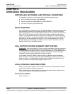
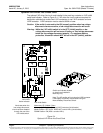
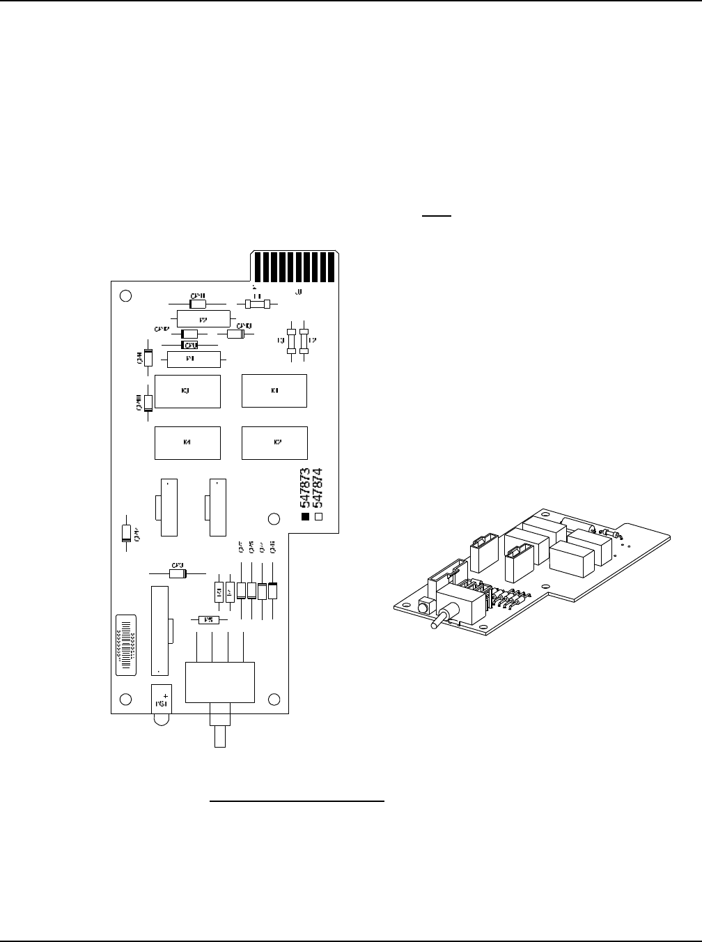
Optional LVD Driver Lite Circuit Card
The optional LVD driver lite circuit card installed in the main bay contains an LVD inhibit
switch and indicator. Refer to Figure 2-4. LVD driver lite circuit cards are required for
distribution cabinets that contain two LVLD contactors or one LVLD contactor and one
LVBD contactor. LVBD contactor must be rated at 600A or lower.
Caution: If the switch is returned to the ON (normal) position when low voltage
disconnect alarms are active, a low voltage disconnection will occur.
Warning: While the LVD inhibit switch is in the OFF (inhibit) position, a low
voltage disconnection will not occur if battery or load voltage decreases
below the low voltage disconnect setpoint. For maximum battery
protection, this switch should NOT be left in the OFF (inhibit) position.
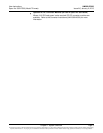
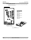
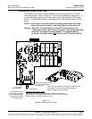
Figure 2-4
Optional LVD Driver Lite Circuit Card
LVD Inhibit Switch
LVD Inhibit
Active Indicator
Momentary UP / Middle / Down
Momentary UP Position: Closes all LVD Contactors (inhibit mode).
Middle Position: OFF (ACU+ DOES NOT control LVD’s) (inhibit mode).
DOWN Position: ON (ACU+ controls LVD’s).
Illuminates when the
low voltage disconnect
circuit has been disabled
through the use of the
LVD Inhibit switch.
J1J3
J2
S1
Note: The UP position will not close the LVBD contactor
if the battery is manually disconnected using the
Manual Battery Disconnect Switch.
Switch and indicator located
on circuit card installed in
Main Bay only.