


UM582127000 User Instructions
Issue AC, January 2, 2013 Spec. No. 582127000 (Model 721NPBB)
Page 18 Chapter 3. Maintenance
This document is property of Emerson Network Power, Energy Systems, North America, Inc. and contains confidential and proprietary information owned by Emerson Network Power, Energy
Systems, North America, Inc. Any copying, use, or disclosure of it without the written permission of Emerson Network Power, Energy Systems, North America, Inc. is strictly prohibited.
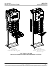
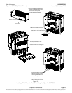
INSTALLING A FIELD EXPANSION RECTIFIER/CONVERTER
MODULE MOUNTING SHELF SPEC. NO. 588705300
Danger: Adhere to the “Important Safety Instructions” presented at the front of
this document.
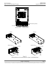
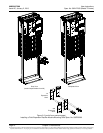
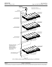
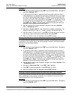
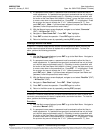
Note: Refer to Figure 3-4 and Figure 3-5 as this procedure is performed.
Procedure
1) Remove the busbar rear shield from the existing rectifier/converter shelves.
Remove the cut-out panel from the busbar rear shield by gently bending the
panel until it snaps from the busbar rear shield.
2) Remove the hardware from the lowest module mounting shelf’s -48V, return, and
+24V (if present) busbars.
3) Install the expansion module mounting shelf directly below the bottom-most
module mounting shelf in the rack. Use the mounting hardware provided with the
expansion module mounting shelf.
Hardware build-up is: 12-24 x 3/4" screw and flat washer, (1) set per side.
12-24 x 3/4" screw and ground washer, (1) set per side.
Note: Install the ground washers so the teeth make contact with the metal on
the mounting angles. Torque all screws to 65 in-lbs.
4) Remove the busbar rear shield from the expansion module mounting shelf.
Note: Apply electrical anti-oxidizing compound to busbar mating surfaces before
performing the next step.
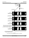
5) Install the busbars provided with the expansion module mounting shelf between
the studs on the expansion module mounting shelf and the studs on the shelf
above it. Secure these busbars to the expansion module mounting shelf with the
hardware provided with the expansion module mounting shelf. Secure these
busbars to the shelf above the expansion module mounting shelf with the
hardware previously removed. Torque to 60 in-lbs.
Hardware build-up for these connections are:
M6 Nut,
M6 Belleville lock washer,
M6 flat washer.
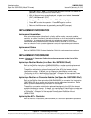
6) Disconnect the cable coming from the distribution cabinet from the connector on
the bottom-most existing module mounting shelf and connect this cable to the
same connector on the expansion module mounting shelf.
7) Connect the open connector on the bottom-most existing module mounting shelf
to the open connector on the expansion module mounting shelf.
8) Re-install the rear busbar shield previously removed from the existing module
mounting shelf. Re-install the rear busbar shield previously removed from the
expansion module mounting shelf.
9) Refer to the Power System Installation Instructions (IM582127000) and connect
AC input power to the expansion module mounting shelf.
10) Refer to the Power System Installation Instructions (IM582127000) and install
rectifier and converter modules into the expansion module mounting shelf as
required.