


User Instructions UM582127000
Spec. No. 582127000 (Model 721NPBB) Issue AC, January 2, 2013
Chapter 4. Troubleshooting and Repair Page 43
This document is property of Emerson Network Power, Energy Systems, North America, Inc. and contains confidential and proprietary information owned by Emerson Network Power, Energy
Systems, North America, Inc. Any copying, use, or disclosure of it without the written permission of Emerson Network Power, Energy Systems, North America, Inc. is strictly prohibited.
to ensure that it cannot be pulled out of the terminal block. Repeat for each wire
to be reconnected.
13) Remove the grounding wrist strap.
14) Close the distribution cabinet’s front door. Turn the latch clockwise to secure the
door.
15) Enable the external alarms, or notify appropriate personnel that this procedure is
finished.
16) Ensure that there are no local or remote alarms active on the system.
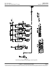
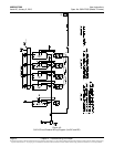
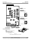
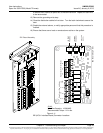
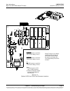
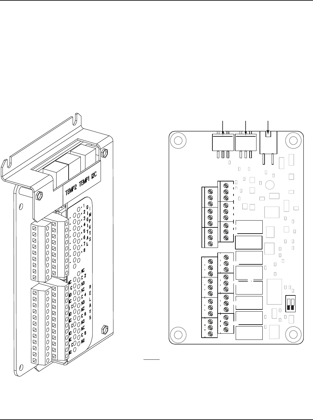
Figure 4-11
IB2 (ACU+ Interface Board) Connector Locations
J3-J9:
Wire Size Capacity: 16-26 AWG.
Recommended Torque: 2.2 in-lbs.
-
J12
*
RELAY
SW1
7
J2
J11
5 3
1
Relay Output Terminal Blocks
Digital Input Terminal Blocks
J9 J8 J7
J6
J5 J4 J3
8
6 4
2
8 7 6 5 4 3
2 1
+
IB2 Board (Top View)
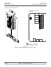
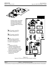
NO
C
NC
NO C NC
NO
C
NC
NO C NC
NO
C
NC
NO C NC
NO
C
NC
NO C NC
5 3 1
46 2
5 3 1
46 2
5
3
1
46 2
5
3
1
46 2
5
3
1
46 2
5 3 1
46 2
5
3
1
46 2
Connector
to ACU+
IB2 TEMP
PROBRE 1
IB2 TEMP
PROBE 2
IB2 Board Assembly