User Instructions UM582127000
Spec. No. 582127000 (Model 721NPBB) Issue AC, January 2, 2013
Chapter 3. Maintenance Page 21
This document is property of Emerson Network Power, Energy Systems, North America, Inc. and contains confidential and proprietary information owned by Emerson Network Power, Energy
Systems, North America, Inc. Any copying, use, or disclosure of it without the written permission of Emerson Network Power, Energy Systems, North America, Inc. is strictly prohibited.
CHANGING THE ACU+ LVD CONTROL
LEVEL FOR A CONTACTOR
The ACU+ Controller has two available LVD control levels (LVD1 and LVD2). The level
used to control a contactor is determined by which connector on the LVD circuit card its
control leads are plugged into. To change the LVD control level for a contactor, simply
switch which LVD connector it is plugged into (if an open connector is available) on the
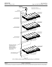
LVD circuit card. Refer to Figure 4-14 and Figure 4-15 for connector location and
function.
Note: DO NOT change a Low Voltage Load Disconnect contactor to LVD Control Level
2 (LVD2) if the system is furnished with a Low Voltage Battery Disconnect
contactor.
ADDING A SUPPLEMENTAL BAY IN THE FIELD
Refer to the Power System Installation Instructions (IM582127000) for procedures
detailing mounting and wiring of the supplemental bay.
Supplied with the supplemental bay is a USB drive which contains a “SettingParam.run”
file. Download this file into the ACU+ Controller to program the ACU+ Controller for use
with the newly installed supplemental bay. Refer to the ACU+ Instructions
(UM1M820BNA) for a download procedure. There are also labels located near the
SM-DU and SM-DU+ in the supplemental bay that detail the ACU+ settings for this bay.
Once the ACU+ has been programmed for the newly installed supplemental bay, refer to
the ACU+ Instructions (UM1M820BNA) and save a copy of the “SettingParam.run” file.


