


User Instructions UM582127000
Spec. No. 582127000 (Model 721NPBB) Issue AC, January 2, 2013
Chapter 4. Troubleshooting and Repair Page 39
This document is property of Emerson Network Power, Energy Systems, North America, Inc. and contains confidential and proprietary information owned by Emerson Network Power, Energy
Systems, North America, Inc. Any copying, use, or disclosure of it without the written permission of Emerson Network Power, Energy Systems, North America, Inc. is strictly prohibited.
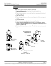
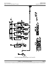
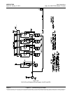
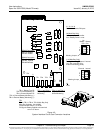
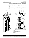
Figure 4-9
System Interface Circuit Card Connector Locations
J1, J2, J3, J4
Distribution Panels FA Inputs
J8 (Main Bay Only)
Selects to power Controller
from “Battery Power” or not.
No
Battery
Pwr
Battery
Pwr
External Internal
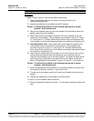
J8
J10
1
2
3
7
8
9
J10 (Main Bay Only)
Battery Monitoring External / Internal
(see TB1-4 and TB1-5 for
external monitoring points)
J5
CAN
TP3 (+) and TP4 (-)
Bay Load
Shunt Monitoring
TP1 (+) and TP2 (-)
Bay Voltage
Monitoring
TB1-1: Battery Tray FA
TB1-2: External Battery FA
TB1-3: External System FA
TB1-4: External Battery Monitoring (-)
TB1-5: External Battery Monitoring (+)
1
1A 2A 3A
1B 2B 3B
5
RS485 Connection
TB2 1A: RS485+
TB2 2A: RS485-
RS232 Connection
TB2 1B: CGND
TB2 2B: TXD232
TB2 3B:RXD232
Shorting Jumper
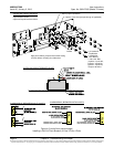
1
2
3
7
8
9
Shorting Jumper
J1
J2
J3
J4
J8
TB2
TB1
TP1 TP2 TP3 TP4
J10
J5
TB1
TB1-2, TB1-3, TB1-4, TB1-5 Main Bay Only.
Wire Size Capacity: 22-12 AWG.
Recommended Torque: 3.0 in-lbs.
FA Signals: Battery applied to the terminal
turns in an alarm.