


User Instructions UM582127000
Spec. No. 582127000 (Model 721NPBB) Issue AC, January 2, 2013
Chapter 3. Maintenance Page 19
This document is property of Emerson Network Power, Energy Systems, North America, Inc. and contains confidential and proprietary information owned by Emerson Network Power, Energy
Systems, North America, Inc. Any copying, use, or disclosure of it without the written permission of Emerson Network Power, Energy Systems, North America, Inc. is strictly prohibited.
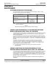
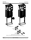
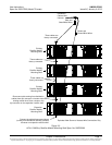
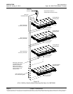
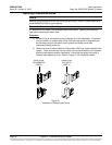
Figure 3-4
Installing a Field Expansion Module Mounting Shelf Spec. No. 588705300
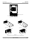
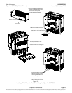
1. Remove busbar rear shield from
existing rectifier/converter shelves.
Remove the cut-out panel
from the busbar rear shield.
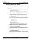
2. Remove hardware from the
lowest module mounting shelf’s
-48V, return, and +24V (if present)
busbars.
3. Install the expansion module
mounting shelf into the rack.
4. Remove busbar rear shield from
expansion module mounting shelf.
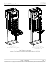
5. Install the busbars provided
with the expansion module
mounting shelf between the
shelves. Torque to 60 in-lbs.
6. Re-install the rear busbar
shields previously removed.
Front
Rear
Busbar Rear Shield
Cut-Out Panel
Rear