


User Instructions UM582127000
Spec. No. 582127000 (Model 721NPBB) Issue AC, January 2, 2013
Chapter 4. Troubleshooting and Repair Page 49
This document is property of Emerson Network Power, Energy Systems, North America, Inc. and contains confidential and proprietary information owned by Emerson Network Power, Energy
Systems, North America, Inc. Any copying, use, or disclosure of it without the written permission of Emerson Network Power, Energy Systems, North America, Inc. is strictly prohibited.
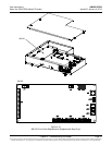
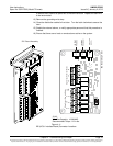
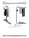
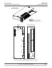
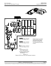
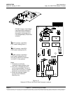
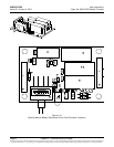
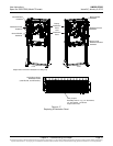
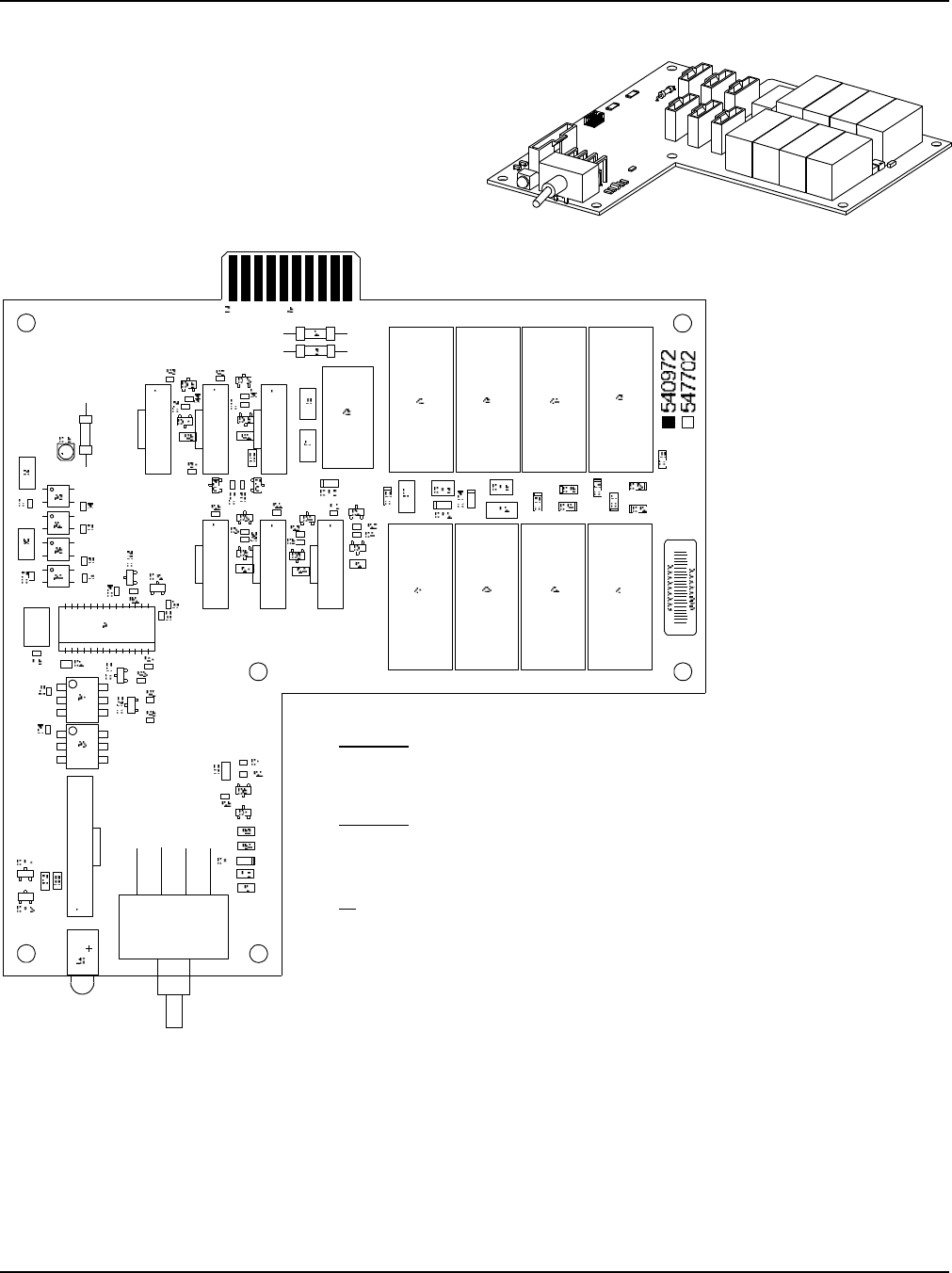
Figure 4-14
Optional LVD Driver Circuit Card Connector Locations
J1, J2, J3
To LVLD contactor, uses ACU+
LVD1 control setting (Level 1).
J4, J5, J6
To LVLD contactor, uses ACU+
LVD2 control setting (Level 2).
J7
To LVBD contactor, uses ACU+
LVD2 control setting (Level 2).
Notes:
1. Connects up to (4) LVLD
and (1) LVBD contactors.
2. Switch and indicator located
on circuit card installed in
Main Bay only.
J6
J5
J4
J3 J2 J1
J7
S1
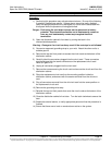
DO NOT change a Low Voltage
Load Disconnect contactor to
LVD Control Level 2 (LVD2) if
the system is furnished with a
Low Voltage Battery Disconnect
contactor.