


UM582127000 User Instructions
Issue AC, January 2, 2013 Spec. No. 582127000 (Model 721NPBB)
Page 10 Chapter 2. Operating Procedures
This document is property of Emerson Network Power, Energy Systems, North America, Inc. and contains confidential and proprietary information owned by Emerson Network Power, Energy
Systems, North America, Inc. Any copying, use, or disclosure of it without the written permission of Emerson Network Power, Energy Systems, North America, Inc. is strictly prohibited.
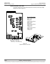
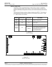
SM-DU Circuit Card
The SM-DU is used in supplemental bays in place of ACU+ controller. The SM-DU
monitors the bay and reports to the controller. The controller sends commands to the
SM-DU to fulfill battery management and load control functions according to the received
data.
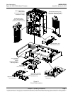
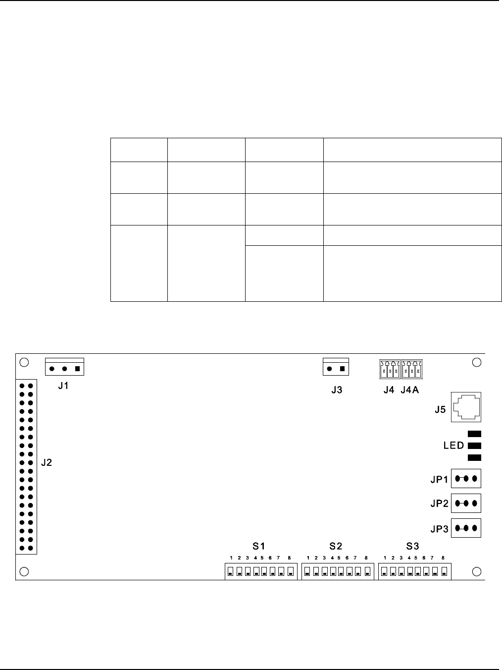
There are three (3) status and alarm indicators located on the SM-DU. The functions of
these indicators (from top to bottom as shown in the illustration) are as shown in Table
2-1. Refer to Figure 2-6 for location.
Indicator
Normal State
Fault State
Fault Cause
Alarm
(Red)
Off
On
A critical or major alarm.
Alarm
(Yellow)
Off
On
A minor alarm.
Operation
(Green)
On
Off
SM-DU is non-operational.
Flashing
A 1/3Hz flashing indicates the SM-DU
is being identified by the Controller.
A 1Hz flashing indicates a
communication failure.
Table 2-1
SM-DU Indicators
Figure 2-6
SM-DU Circuit Card