


User Instructions UM582127000
Spec. No. 582127000 (Model 721NPBB) Issue AC, January 2, 2013
Chapter 3. Maintenance Page 11
This document is property of Emerson Network Power, Energy Systems, North America, Inc. and contains confidential and proprietary information owned by Emerson Network Power, Energy
Systems, North America, Inc. Any copying, use, or disclosure of it without the written permission of Emerson Network Power, Energy Systems, North America, Inc. is strictly prohibited.
CHAPTER 3.
MAINTENANCE
SYSTEM MAINTENANCE PROCEDURES
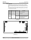
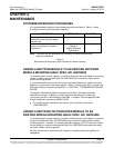
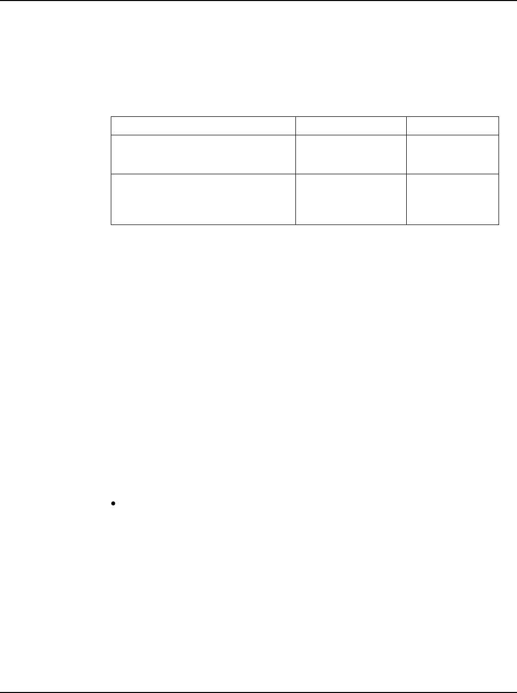
It is recommended to perform the maintenance procedures listed in Table 3-1 every
6-months to ensure continual system operation.
PROCEDURE
REFERENCED IN
COMPLETED (√)
Check ventilation openings for
obstructions such as dust, papers,
manuals, etc.
--
Inspect and tighten all installer's
connections.
IM582127000,
Chapter 4.
Making Electrical
Connections.
Note: This table may be reproduced as necessary to record and document
system performance.
Table 3-1
Maintenance Procedures to be Performed at 6-Month Intervals
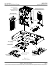
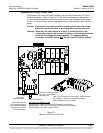
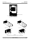
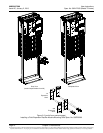
ADDING A RECTIFIER MODULE TO AN EXISTING RECTIFIER
MODULE MOUNTING SHELF SPEC. NO. 588705000
To increase system current capacity, a rectifier module can easily be added to an existing
rectifier module mounting shelf Spec. No. 588705000 that contains an empty rectifier
module mounting position.
It is recommended that the current limit point be checked whenever a rectifier module is
added to or removed from the power system. Refer to “Checking the ACU+ Current Limit
Point after Adding or Removing a Rectifier” in “CHAPTER 4. TROUBLESHOOTING AND
REPAIR”.
The rectifier module being added is assigned by the ACU+ the lowest available
identification number. If desired, you can change the identification number, see
“Configuring the ACU+ Identification of Rectifiers” in Chapter 5 of the separate Power
System Installation Instructions (IM582127000).
For rectifier module installation instructions, refer to Rectifier Instructions
(UM1R483500E).
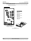
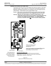
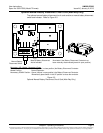
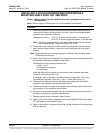
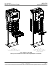
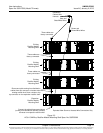
ADDING A RECTIFIER OR CONVERTER MODULE TO AN
EXISTING MODULE MOUNTING SHELF SPEC. NO. 588705300
To increase system current capacity, a rectifier module can easily be added to an existing
module mounting shelf Spec. No. 588705300 that contains an empty rectifier module
mounting position. Likewise, to increase subsystem capacity a DC-DC converter module
can be added to a module mounting shelf Spec. No. 588705300 that contains an empty
converter module mounting position.
Rectifier and converter modules can be inserted or removed with power applied (hot
swappable).