


RTM‐ATCA‐SXXXInstallation
6806800H62B ATCA‐S201InstallationandUseGuide127
Handling modules and peripherals can result in static damage. Use a grounded wrist
strap, static-dissipating work surface, and antistatic containers when handling and
storing components.
Insert the board by holding the Module Handles–do not exert unnecessary pressure
on the faceplate.
Hot swap compliant modules may be installed while the system is powered on. If a
module is not hot swap compliant, you should remove power to the slot or system
before installing the module.
5. Verify that you have taken the necessary antistatic precautions.
6. Go to the back of the system and choose an appropriate slot for the rear
transition module.
Rear transition modules must be installed in-line behind the accompanying
node board. For example, if the accompanying node board is going to be
installed in slot 3, its rear transition module must be installed at the back of the
system in slot 3.
7. Remove the slot filler panel from the selected node board slot, if necessary.
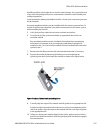
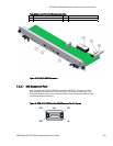
8. Prepare the module by loosening the locking screws and opening the
injector/ejector latch at the top of the module as shown in the figure below.
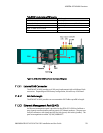
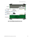
Figure 41 Injector / Ejector Latch and Locking Screw
9. Carefully align the edges of the module with the guides in the appropriate slot.
It might be helpful to look into the enclosure to verify correct alignment of the
rails in the guides. Align the edges of the module with the card cage rail guides
in the appropriate slot.
10. Taking care to keep the module aligned in the guides, apply equal and steady
pressure and slide the module in until the injector/ejector mechanism engages
the retention bars.