


RTM‐ATCA‐SXXXMechanicalandConnectorInformation
6806800H62B ATCA‐S201InstallationandUseGuide137
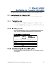
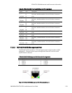
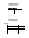
Table 69 Connector J33, Miscellaneous RTM Signal Descriptions
PS0# Active low RTM present signal.PS0# is tied to logic GND on the ATCA blade. PS0# (Connector
J33) and PS1# (Connector J30) shall be connected through a diode on the RTM, exactly as
defined in AMC.0 specification. PS1# is last mate on Power connector and PS0# is on the
opposite end of the set of connectors. Logic low on PS1# indicates that RTM is present and
fully inserted
ENABLE# When low indicates to RTM that it is fully inserted and that MMC can start execution. Logic
high shall keep MMC in reset state. This signal shall have a pull-up resistor as indicated in
AMC.0 specification.
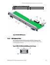
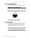
13.2.4.3 Connector J30, Power Supply for Advanced RTM
The RTM-ATCA-SXXX supplies 12V and the 3.3V stand-by voltages to an Advanced
rear transition modules (RTM) via the P30 connector. The P30 connector
assignments also include the IPMI-L interface, PS1#. If needed, an Advanced RTM
will convert the main 12V payload power into 1.2V, 1.5V, 2.5V and 3.3V by using
DCDC converters.
The RTM-ATCA-SXXX P30 connector is implemented with the Metral® 89096-xxx
from FCI (www.fciconnect.com
).
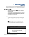
e
d
c
b
a
J30- ATCA
2 1
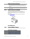
Figure 47 ‘J30’ RTM Power Receptacle
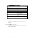
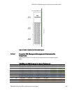
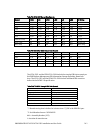
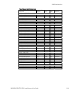
13.2.4.4 Connector J30, RTM Power Pin Assignment
The RTM-ATCA-SXXX J30 connector pin assignments and descriptions appear below.
Table 70 J30, RTM Power Pin Header Assignment
Row# Interface 1 2
e Pwr PS1# NC
d Pwr +12V PP +12V PP
c IPMI IPMI_SCL_L IPMI_SDA_L
b Pwr Logic_GND +3.3V MP
a Pwr Logic_GND Shelf_GND