


ATCA‐S201Installation
6806800H62B ATCA‐S201InstallationandUseGuide17
2. Go to the front of the system and choose an appropriate slot for the ATCA
carrier blade.
If also installing a companion advanced rear transition module (RTM), install it
before installing the ATCA node board. For example, if the ATCA node board is
planned for slot B4, first install the ARTM at the back of the system in slot B4.
3. Remove the slot filler panel from the selected node board slot, if necessary.
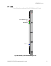
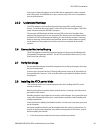
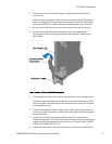
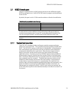
4. Prepare the module by loosening the locking screws and opening the
injector/ejector latch at the top and bottom of the module as shown in the
figure below.
Figure 4 Injector / Ejector latch and locking screw
5. Carefully align the edges of the module with the guides in the appropriate slot.
It might be helpful to look into the enclosure to verify correct alignment of the
rails in the guides. Align the edges of the module with the card cage rail guides
in the appropriate slot.
6. Taking care to keep the module aligned in the guides, apply equal and steady
pressure and slide the module in until the injector/ejector mechanism engages
the retention bars.
7. Position your thumbs at the top and bottom of the ATCA carrier board;
simultaneously push in the module and rotate the injector/ejector mechanisms
inward to their closed position to seat and secure ATCA carrier blade. DO NOT
FORCE THE BOARD INTO THE SLOT.
8. Tighten the two module retention screws to secure the module into the shelf.