


EPSON EPL-N2700 Rev. A
Chapter 4 Disassembly/Assembly 107
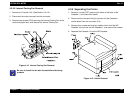
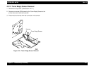
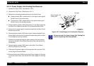
4.2.15 Power Supply Unit Cooling Fan Removal
1. Remove the Rear Cover. (See Section 4.2.6.)
2. Remove the Top Cover. (See Section 4.2.11.)
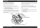
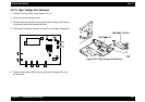
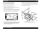
3. Remove the following screws and remove the Shield Cover.
Sixteen screws (3501: marked with A in the figure) securing the
Shield Cover to the printer frame.
Three screws (1305: marked with B in the figure) securing the
Shield Cover to the Interface bracket.
4. Remove twelve screws (1305: marked with C in the figure) securing
the Main Circuit Board to the Main Circuit Board Mounting Plate.
5. Disconnect the control panel harness connecting to the Main Circuit
Board from the CN3.
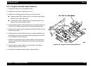
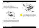
6. Remove seven screws (1305) securing the Interface bracket to the
printer frame, and remove the Interface bracket along with the Main
Circuit Board by moving it upward.
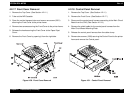
7. Remove one screw securing the shield cable for the control panel
harness to the Main Circuit Board Mounting Plate, and remove the
shield cable.
8. Remove twelve screws (1305) securing the Main Circuit Board
Mounting Plate to the P/H Plate.
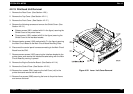
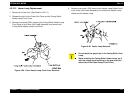
9. Disconnect the power supply unit harness from the connector P/J6
on the Engine Controller Board.
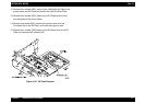
10. Remove two screws (3435) securing the Power Supply Unit Cooling
Fan to the printer frame, and remove the Power Supply Unit Cooling
Fan.
Figure 4-27. Power Supply Unit Cooling Fan Removal
CHECK
POINT
Be sure to install the Power Supply Unit Cooling Fan
with its exhausting side facing outside.
Harness
Power Supply Unit
Cooling Fan