


EPL-N2700 Revision A
Operating Principles Printer Mechanism Operating Principles 68
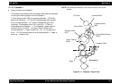
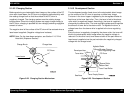
2.1.6 Imaging Cartridge
2.1.6.1 Part Names and Functions of the Imaging Cartridge
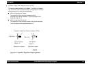
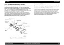
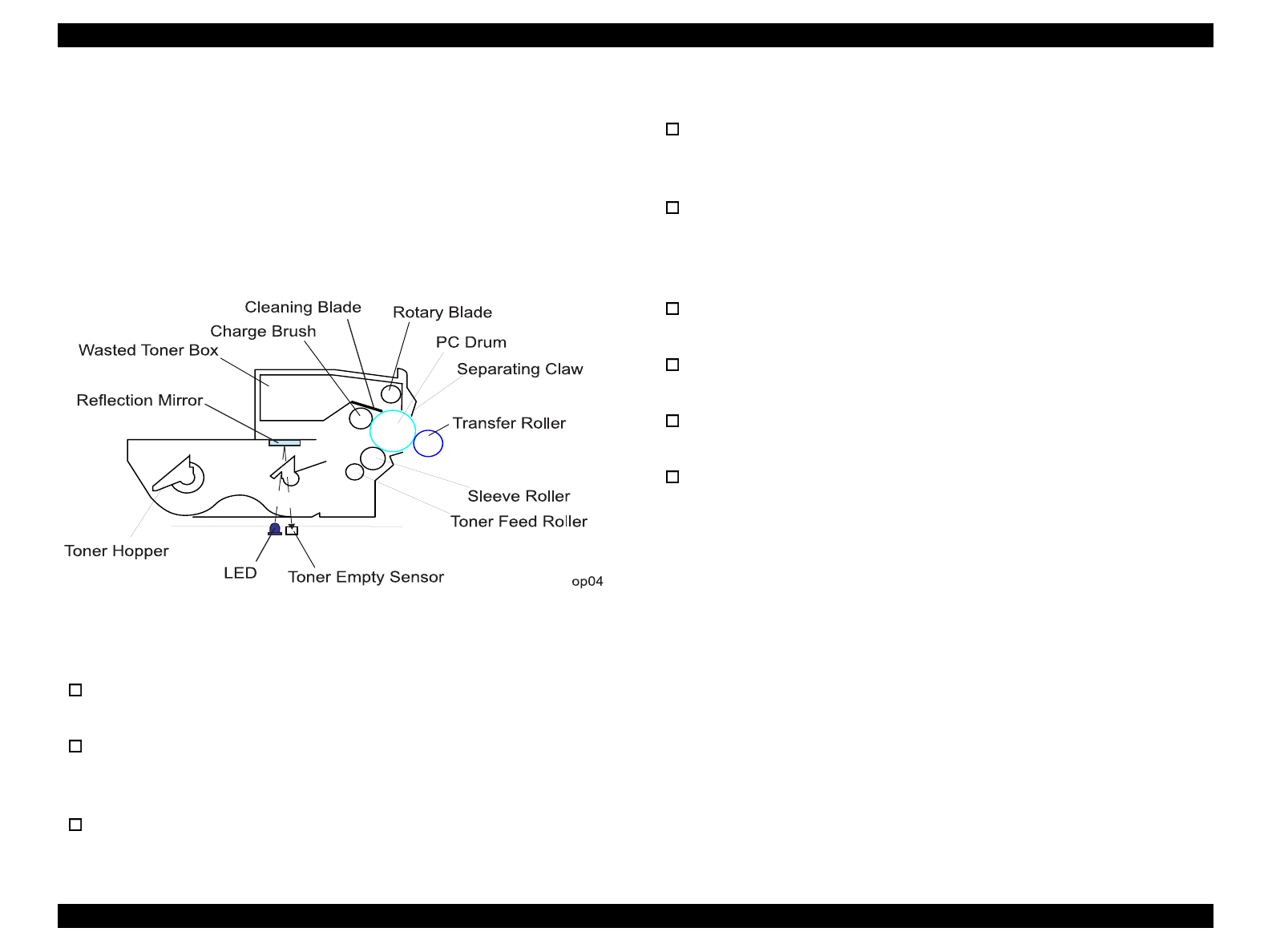
The following illustrates the construction of the imaging cartridge. The
power to the gears of the imaging cartridge is transmitted from the I/C
drive motor (M1) of the printer main body. The I/C drive motor (M1)
turns clockwise viewing from the front of the printer.
Figure 2-21. Imaging Cartridge
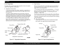
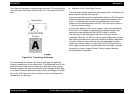
Charge Brush: Charges the PC Drum. By using the
brush, less ozone is emitted.
Toner Hopper: Agitates toner with the two agitator
blade to feed toner to the toner feed
roller.
Toner Feed Roller: Feeds toner to the sleeve roller.
Sleeve Roller: Feeds toner to the electrostatic latent
image formed on the surface of the PC
drum to produce a visible toner image.
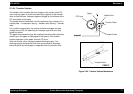
Transfer Roller: Transfers the toner image on the
surface of the PC drum onto the paper.
(The transfer roller is not incorporated
in the imaging cartridge.)
Separating Claw: Securely separates the paper from the
PC drum.
Cleaning Blade: Cleans off the toner remaining on the
surface of the PC drum.
Rotary Blade: Feeds the wasted toner to the wasted
toner box.
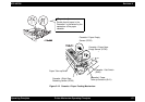
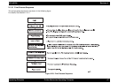
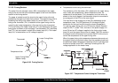
Toner Empty Sensor: Detects a toner-empty status. (The
toner empty sensor is not incorporated
in the imaging cartridge.) The sensor
unit consists of the LED and the sensor.
Light emitted from the LED is reflected
by the reflection mirror built in the
imaging cartridge and then detected by
the sensor. the sensor monitors the
toner’s empty/near empty condition by
referring to the voltage level, pulse
width, and detected times of the
detection signal.