


Confidential
EPSON
TITLE
SHEET
REVISION
NO.
SHEETNEXT
B
App.10 App.9
TM-T88III series
Specification
(STANDARD)
APPENDIX F: NOTES ON USING THE DRAWER KICK-OUT
CONNECTOR
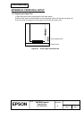
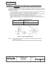
1) Drawer kick-out connector use conditions (refer to Section 2.2.3, Drawer kick-out connector)
Because drawer specifications differ depending the manufacturer and the part number, make sure
that the specifications of the drawer to be used meet the following conditions before connecting it
to the drawer kick-out connector. These conditions also apply to any other devices that use the
drawer kick-out connector.
Any devices that do not satisfy all the following conditions must not be used.
[Conditions]
• A load must be provided between drawer kick-out connector pins 4 and 2 or between pins 4
and 5. (Operating the printer with incorrectly installed devices voids the warranty.)
• When the drawer open/close signal is used, a switch must be provided between drawer
kick-out connector pins 3 and 6. (Connecting devices other than the drawer open/close
switch voids the warranty.)
• The resistance of the load must be 24 Ω or more, or the input current must be 1 A or less. (If
a device with a resistance of less than 24
Ω or an input current of over 1 A is used, the
resulting overcurrent may damage the printer and the device.)
• Be sure to use drawer kick-out connector pin 4 (24 V power output) to drive the device.
Never connect any other power supply to the drawer kick-out connector. (Connecting a
power supply other than that specified voids the warranty.)
The peak current is 1 A. When energizing the drawer kick-out drive signal, follow the
conditions described in 3) of Section 2.2.3,
Drawer kick-out drive signal.