


Principles of Operation
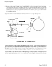
Figure 6-8. Push-pull Tractor Operation Using the
Rear Paper Entrance
........................................................
6-10
Figure 6-9. Push-pull Tractor Operation Using the
Front Paper Entrance
.......................................................
6-11
Figure 6-10. Release Lever
....................................................................
6-12
Figure 6-11. Release Lever Setting Functions
......................................
6-12
Figure 6-12. Paper Path for Friction Feeding Using the
Top Entrance
.....................................................................
6-13
Figure 6-13. Paper Path for Push Tractor Feeding Using the
Rear Entrance
.....................................................................
6-14
Figure 6-14. Paper Path for Pull Tractor Feeding Using the
Rear Entrance
...................................................................
6-14
Figure 6-15.
Paper Path fbr Push-pull Tractor Feeding Using the
Rear Entrance
.....................................................................
6-15
Figure 6-16.
Paper Path for Pu11 Tractor Feeding Using the
Bottom Entrance
.................................................................
6-15
Figure 6-17. Paper Path for Friction Feeding Using the
Front Entrance
..................................................................
6-16
Figure 6-18. Paper Path for Push Tractor Feeding Using the
Front Entrance
....................................................................
6-16
Figure 6-19. Paper Path for pull Tractor Feeding Using the
Front Entrance
..................................................................
6-17
Figure 6-20.
Paper Path for Push-pull Tractor Feeding Using the
Front Entrance
....................................................................
6-17
Figure 6-21. Ribbon Advance Mechanism
.............................................
6-18
Figure 6-22. Power Supply Circuit Block Diagram
...............................
6-21
Figure 6-23. Control Circuit Block Diagram
.........................................
6-22
Figure 6-24. Data Flow
..........................................................................
6-23
Figure 6-25. Power On Reset Circuit
....................................................
6-25
Figure 6-26. Sensor Circuit Block Diagram
..........................................
6-26
Figure 6-27. Carriage Motor Drive Circuit
...........................................
6-27
Figure
6-28.
Paper Feed Motor Drive Circuit
.......................................
6-28
Figure 6-29. Printhead Drive Circuit
....................................................
6-29
Figure 6-30. Parallel Interface Circuit
..................................................
6-29
Figure 6-31.
E2PROM
Control Circuit
...................................................
6-30
List of Tables
Table 6-1.
Paper Feed Methods
and Paper Entrances
........................ 6-5
Table 6-2.
Ribbon Advance Gear Linkage
.........................................
6-18
Table 6-3.
Power Supply Input Voltage and Fuse Rating..
...............
6-19
Table 6-4.
Power Supply Output Voltages and Applications
............
6-19
Table 6-5.
Functions of Main Components of C094 MAIN
...............
6-24
6-ii
Epson FX-870/1170