


Principles of Operation
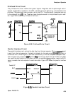
Reset Circuit
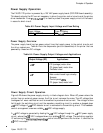
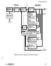
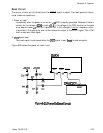
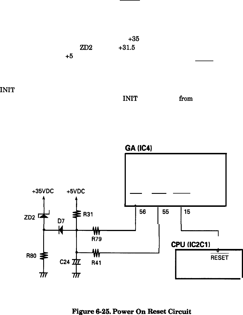
The control circuits are initialized when the RESET signal is issued. The reset operation occurs
under these two conditions:
1. Power on reset
Immediately after the power is turned on,
+35
VDC is rapidly generated. Because it takes a
moment for the voltage at
ZD2
to reach
+31.5
V, the voltage at the DISC terminal on the gate
array does not reach +5 VDC until capacitor C24 is fully charged. A similar integration circuit
is provided in the gate array and further delays the output of the ROUT signal. This LOW
level is used as a reset signal.
2. INIT signal reset
The reset signal is also issued when the INIT signal is sent
from
the host computer.
Figure 6-25 shows the power on reset circuit.
GA
(IC4)
+35VDC
+5VDC
-
-
t
t
RIN
DISC ROUT
I
I
I
-
ZD2+
D7
gR31
156
l55
I5
CPU
~IC2ClI
I
15
Figure
6-25.
Power
On
Reset
Circuit
Epson FX-870/1170
6-25