


Disassembly and Assembly
Removing the Printer Mechanism
1.
2.
3.
4.
5.
6.
7.
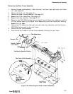
Remove the paper guide assembly, ribbon, top cover, front cover, paper eject cover, and tractor
unit. (See page 4-5.)
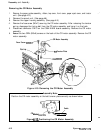
Remove the panel unit. (See page 4-6.)
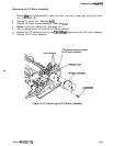
Remove the upper housing assembly. (See page 4-8.)
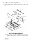
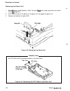
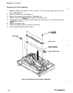
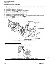
Remove the four CBB (M4x12) screws securing the printer mechanism.
Remove the CBS (M3x6) screw securing the interface cover.
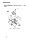
Disconnect the following connectors on the MAIN board assembly: CN3 (a-pin, BLUE), CN4
(a-pin,
WHITE), CN5
(2-pin,
BLACK), CN6
(6pin,
BLACK), CN7
(a-pin,
YELLOW), CN8
(lCpin,
FFC cable),
CN9
(&pin, WHITE), CN12 (lo-pin, control panel), and CN13
(5-pin,
WHITE).
Remove the printer mechanism.
CBB
k4X12)
Interface Cover
Printer Mechanism
Figure
4-7.
Removing
the
Printer
Mechanism
Epson
FX-870/1170
4-9