


Printer Features
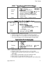
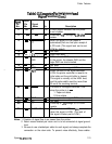
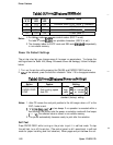
Table
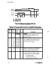
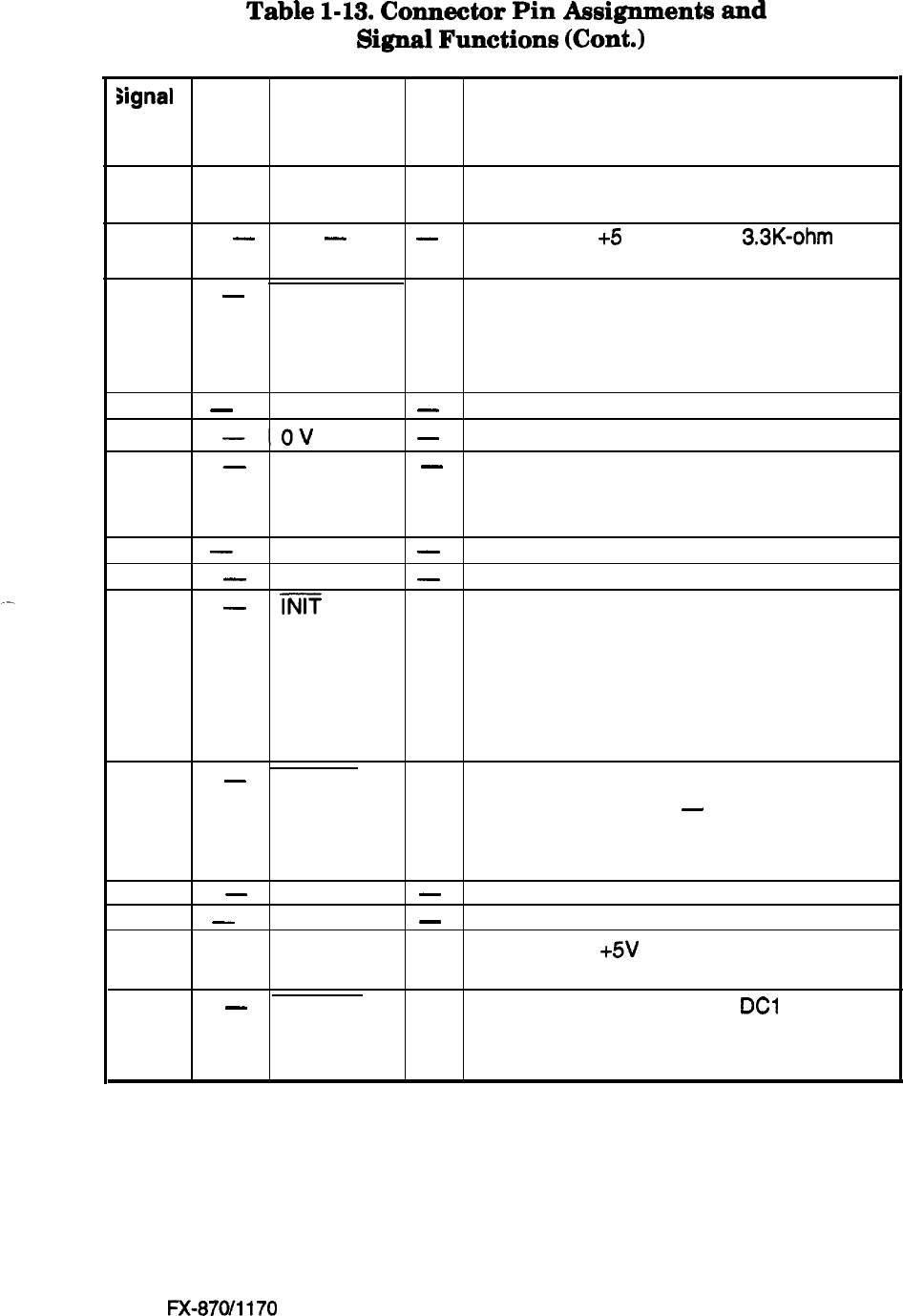
1-13.
Connector
Pin
Assignments
and
Signal
Functions
(Cont.)
signal
Return
Pin
Pin
Signal
No. No.
Name
Dir.
Description
12
30 PE
Out A HIGH signal indicates that the printer
is out of paper.
.
13
-
-
-
Pulled up to
+5
V through a
3.3K-ohm
resistor.
14
-
AUTO FEED In
When this signal is LOW, paper is
XT
automatically fed one line upon receipt of
a CR code. (This signal level can be set
LOW by default.)
15
-
NC
-
Not used.
16
-0V
-
Logic GND level.
17
-
CHASSIS
-
Printer chassis GND.
GND
In the printer, the chassis GND and the
logic GND are short-circuited.
18
-
NC
-
Not used.
9
to
30
-
GND
-
Twisted-pair return signal GND level.
31
-
im
In
When the level of this signal becomes
LOW, the printer controller is reset to its
initial state and the print buffer is cleared.
This signal is normally at the HIGH level,
and its pulse width must be more than
50 us at the receiving terminal.
32
-
ERROR Out
The level of this signal becomes LOW
when the printer is in
-
1. Paper-out status
2. Error status
33
-
GND
-
Twisted-pair return signal GND level.
34
-
NC
-
Not used.
35 --
-
Pulled up to +5V through a 3.3 K-ohm
resistor.
36
-
SLCT IN In
The data between DC3 and
DC1
is invalid
when this signal is HIGH. (The level of
this signal is factory set to LOW.)
Notes:
1. Direction of signal flow is as viewed from the printer.
2. Return means twisted pair return and is to be connected at signal ground
level.
3.
Be sure to use a twisted-pair cable for each signal, and always complete the
connection on the return side. To prevent noise effectively, these cables
Epson
FX-870/1170
1-15