


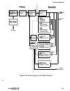
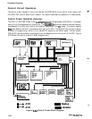
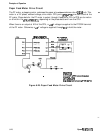
Principles of Operation
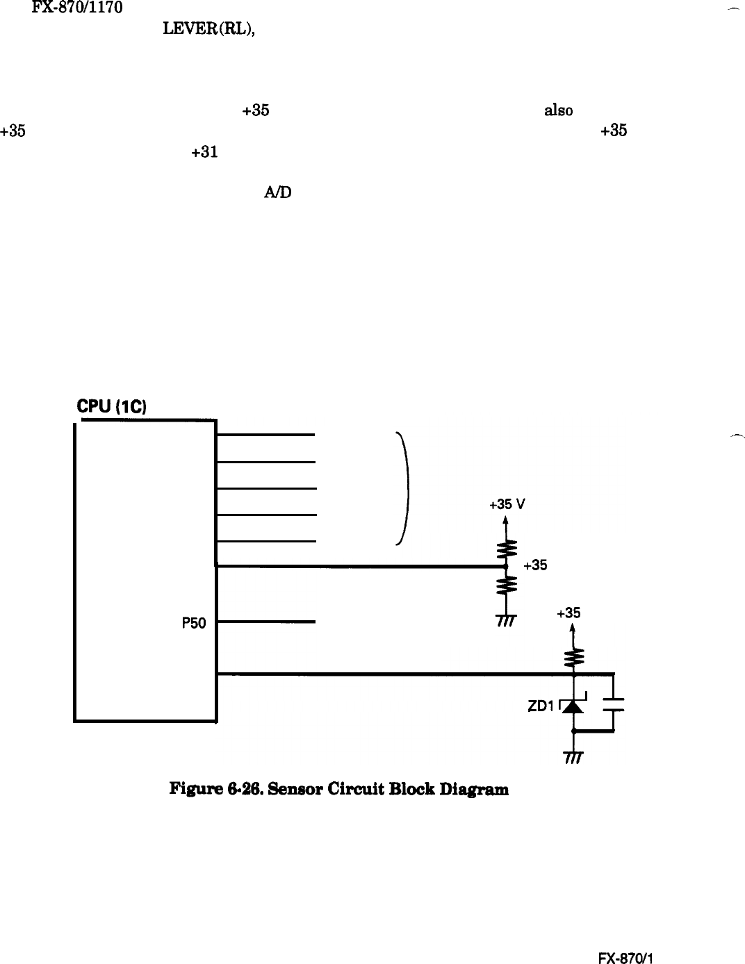
Sensor Circuits
The
FX-8’70/1170
printer has the following sensors: CRHOME, PE (FRONT), PE (REAR), PG
(platen gap), RELEASE
LEVER(RL),
and HEAD TEMPERATURE. All the sensors are mechanical
switches, except the rear PE sensor, which is a photo diode, and the HEAD TEMPERATURE
sensor, which is a thermistor.
-
In addition to the sensor circuits, a
+35
V monitor circuit and a Vref circuit are also provided. The
+35 V monitor circuit sets the pulse length of the head drive signal.
If the voltage of the +35 V line
drops below approximately
+31
V, the printer stops printing for a while.
As soon as the voltage
recovers, the printer starts to print at halfspeed. (The PF motor also slows down.) The Vref circuit
supplies the reference voltage for the A/D convertor in the CPU.
The CPU constantly monitors the printhead temperature. If the printhead temperature exceeds
the maximum level, the printer stops printing until the temperature drops to a certain level. When
the printhead temperature cools down, the printer resumes printing automatically.
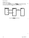
Figure 6-26 shows the sensor circuit block diagram.
CPU
(1C)
P55
P52
P53
P34
P31
CRHOME
PE FRONT
PE REAR
PG
RELEASE
LEVER
P51P51
P50P50
VrefVref
Head TemperatureHead Temperature
+35
Voltage Monitor
+35
Voltage Monitor
+35
v
+35
v
VrefVref
ZDl
-.
Figure
6-26.
Sensor
Circuit
Block
Diagram
6-26
Epson FX-8700 170