


Printer Features
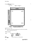
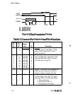
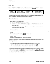
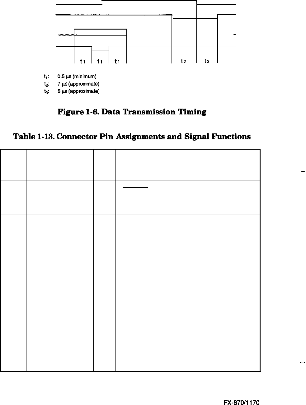
BUSY
I
ACKNLG
DATA
p
. . . .
. . . . . . . . . . . .
-.-
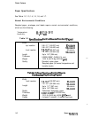
STROBE
-
t1
t1
t1
t2 t3
t,:
0.5
p-s
(minimum)
t2:
7
w
(approximate)
5:
5
w
(approximate)
Figure
1-6.
Data
Transmission
Timing
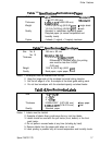
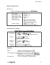
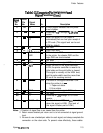
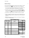
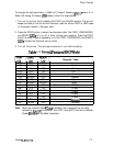
Table
1-13.
Connector
Pin
Assignments
and
Signal
Functions
Signal Return
Pin
Pin
Signal
No. No.
Name
Dir.
Description
1
19
STROBE In
STROBE pulse to read data in. Pulse
width must be more than 0.5 us at
receiving terminal.
2
20
DATA 1 In
These signals represent the 1st to 8th
3
21
DATA2 In
bits of parallel data, respectively. Each
4
22
DATA3 In
signal is HIGH when data is a logical 1
5
23
DATA4 In
and LOW when a logical 0.
6
24
DATA5 In
7
25
DATA6 In
8
26
DATA7 In
9
27
DATA8 In
10
28 ACKNLG
out
Approx. 12 us pulse. LOW indicates that
data has been received and that the
printer is ready to accept more data.
11
29
BUSY
out
A HIGH signal indicates that the printer
cannot receive more data. The signal
becomes HIGH in the following cases:
1. During data entry
2. During input buffer full
3. During printer error status
-
-
1-14
Epson
FX-870/1170