


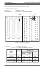
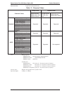
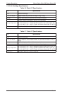
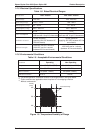
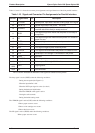
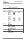
Table 1-10 and 1-11 shows the connector pin assignments and signal functions of the 8-bit parallel interface.
Table 1-10. Signal and Connector Pin Assignments for Parallel Interface
Pin No. Signal Name I/O* Description
1 -STROBE I Strobe pulse. Input data is latched at falling edge of the signal.
2-9 DATA 1-8 I Parallel input data to the printer. bit 0:LSB
10 -ACKNLG O
This signal (negative pulse) indicates that the printer has
received data and is ready to accept next one.
11 BUSY O
This signal’s high level means that the printer is not ready to
accept data.
12 PE O
This signal’s hugh level means that the printer is in a state of
paper-out error.
13 SLCT O Always at high level when the printer in powered on.
14 -AFXT I Not used
31 -INIT I This signal’s negative pulse initializes printer.
32 -ERROR O This signal’s low level means the printer is in a state of error.
35 +5 V —
Pulled up to +5 V through 1.0 KΩ resistor in the printer.
36 -SLIN In Not used.
17 CHASSIS —- Chassis ground
18 Logic H O
Pulled up to +5V through 3.9 KΩ resistor.
16,33
19-30
GND — Signal ground.
15,34 NC —- Not connected.
* The I/O column indicates the direction of the signal as viewed from the printer.
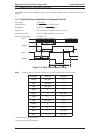
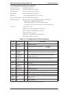
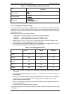
The busy signal is active (HIGH) under the following conditions:
-During data reception(See Figure 1-6)
-When the input buffer is full
-When the-INIT input signal is active (low level)
-During the hardware initialization
-When the-ERROR or PE signal is active
- During the self-test mode
-During the default setting mode
The -ERROR signal is active(LOW) under the following conditions:
-When a paper-out error occurs
-When a no ink catridge error occurs
-When a fatal error occurs
The PE signal is active (HIGH) under the following conditions:
-When a paper-out error occurs
Product Description Epson Stylus Color 200 /Epson Stylus 200
1-10 Rev. A