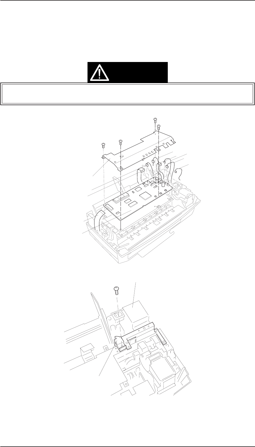
3.2.2 C199 MAIN Control Board and ASF Sensor Removal
1. Remove the upper case (see Section 3.2.1).
2.
Remove 4CBB (M3×6) screws attaching the shield frame to the C160 MAIN Board.
3. Remove 7 connectors (CN1, CN8, CN7, CN4, CN3, CN5, CN6) on the main board. (Push CN6 down to
release cable on main board.) Then remove the C199 Main Control Board.
4. Remove a CBB (M3x6) screw fixing a ASF Sensor holder to printer mechanism.
When you replace the C199 MAIN Board, reset the EEPROM and perform the required
adjustments. (See Chapter 4.)
CBB(M3x6)
C160 PSB/PSE Board
ASF Sensor Holder
Figure 3-3. ASF Sensor Removal
CBB(M3x6)
CBB(M3x6)
CBB(M3x6)
CBB(M3x6)
Shield Plate
CN1
CN8
CN7
CN4
CN3
CN5
CN6
C199 Main Board
CN9
Figure 3-2. C199 Main Board Removal
CAUTION
EPSON Stylus Color 200 / EPSON Stylus 200 Disassembly and Assembly
Rev. A 3-3


