


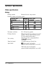
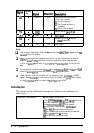
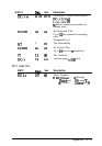
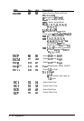
Signal Return
Pin
Pin
Slgnul
Direction
Description
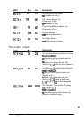
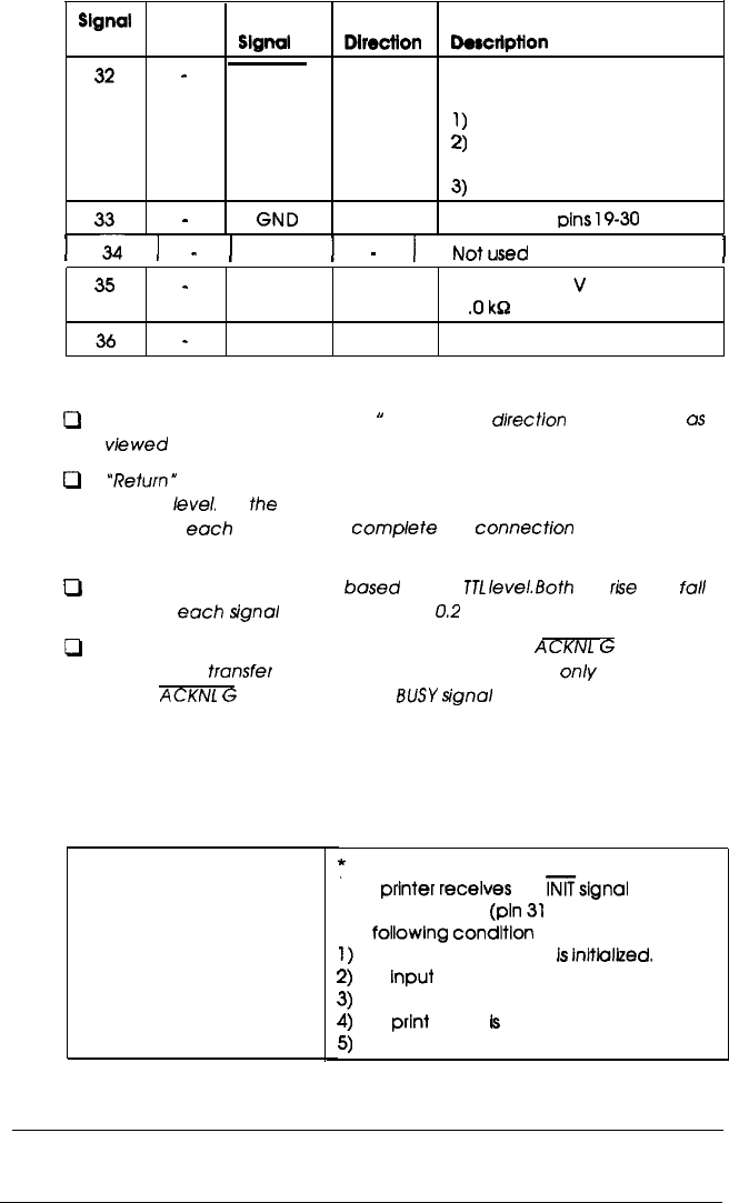
32
-
ERROR
OUT This level becomes LOW
when the printer:
1)
Is out of paper
2)
The Pause button is
pressed
33
-
GND
3)
Is In an error state
Same as for
pins
19-30
1
-ii
1
-
1
NC
1
-
1
Notused
I
35
-
OUT
Pulled up to 5
V
through
1
.O
kg resistance
36
-
NC
IN
Not used
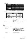
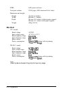
Note:
Cl
cl
cl
0
The column heading “Direction
”
refers to the
direction
of signal flow
OS
viewed from the printer.
“Return”
denotes the twisted-pair return, to be connected at signal
ground
level.
For
the
interface wiring, be sure to use a twisted-pair
cub/e for each signal and to complete the connection on the return
side.
A//interface conditions are
based
on the
TJL
level.
Both
the
r!.se
and full
times of each signal must be less than
0.2
microseconds.
Data transfer must be carried out by observing the
ACKNl
G
or BUSY
signal. Data transfer to this printer can be carried out only after receipt
of the
ACKNl
G
signal or when the BUSY signal is LOW.
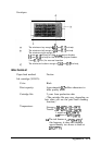
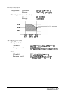
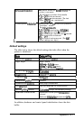
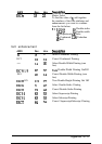
Initialization
The printer can be initialized (returned to a fixed set of conditions) in
three ways:
Hardware initialization
:
The power is turned on.
*The
printer
receives
an
Ksignal
from the
parallel interface
(pln
31
goes LOW).
The
followlng
condltlon
then results:
1)
The printer mechanism
Is
Lnltialized.
2)
The
Input
data buffer Is cleared.
3)
The download character set is cleared.
4)
The
print
buffer
Is
cleared.
5)
The default values are set.
A-10 Appendix