


Pressure Systems, Inc. NetScanner™ System (9016, 9021, & 9022) User’s Manual
www.PressureSystems.com
- x -
List of Figures
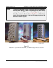
Figure 1.1 NetScanner System Pneumatic Intelligent Pressure Scanners ........ 1-2
Figure 2.1 9016, 9021, 9022 Power Pin Assignments ...................... 2-2
Figure 2.3 Ethernet Host Port Connector Pins ............................ 2-3
Figure 2.3 Ethernet Network Topology .................................. 2-5
Figure 2.4 9021 Transducer Wiring ................................... 2-10
Figure 2.4a 9022 Transducer Wiring ................................... 2-10
Figure 2.5 9022 Jumper Set for 10 VDC Excitation ....................... 2-11
Figure 4.1 Calibration Manifold RUN Position ........................... 4-2
Figure 4.2 Calibration Manifold CAL Position ............................ 4-2
Figure 4.3 Calibration Manifold PURGE Position ......................... 4-2
Figure 4.4 Calibration Manifold LEAK CHARGE Position ................. 4-2
Figure 4.5 9021 and 9022 Voltage Input Connections ..................... 4-11
Figure 5.1 Exploded View of 9016 and 9022 ............................. 5-1
Figure 5.1a 9016 Top Plate ............................................ 5-2
Figure 5.2b 9021 Top Plate ............................................ 5-2
Figure 5.2c 9022 Top Plate ............................................ 5-2
Figure 5.2 9016 Scanner Out of Housing ................................ 5-4
Figure 5.2a 9022 Scanner Out of Housing ................................ 5-4
Figure 5.3 PC-203 Board ............................................. 5-6
Figure 5.3a 9022 PCBs Outside the Housing .............................. 5-7
Figure 5.3b 9022 PCBs Apart .......................................... 5-7
Figure 5.4 Top View of DH200 ....................................... 5-9
Figure 5.5 Solenoid in Module ....................................... 5-10
Figure 5.6 DH200 Transducer O-Ring Replacement ...................... 5-11
Figure 5.7 Solenoid Valve O-Ring Replacement ......................... 5-15
Figure 5.8 PC-317 Board (Trim Potentiometer and Jumper) ................ 5-16
Figure 5.9 Update Firmware Screen ................................... 5-18
List of Tables
Table 2.1 Diagnostic Port Wiring ..................................... 2-6
Table 3.1 Error Codes .............................................. 3-5
Table 3.2 Intelligent Pressure Scanner Commands ....................... 3-10
Table 5.1 Component Cross Reference ................................. 5-2