


Pressure Systems, Inc. NetScanner™ System (9016, 9021, & 9022) User’s Manual
www.PressureSystems.com
5 - 5
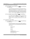
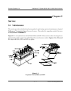
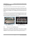
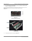
Figure 5.2
9016 Scanner Out of Housing
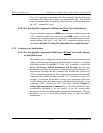
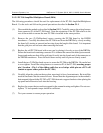
Figure 5.2a
9022 Scanner Out of Housing
5.1.2 Module Disassembly
The following procedure should be used to disassemble any model prior to any maintenance:
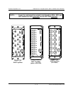
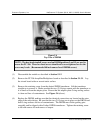
(1) Place the scanner with its external connectors facing up. With one hand holding the module
housing, remove all screws securing the top plate to the module housing. These are located around
the outer edge of the top panel of the module housing. For 9021 scanners these will be six (6) 4-40
Allen-head screws which require a 3/32" Allen driver (for 9022 scanners, there are twelve (12)
Phillips-head screws). The 9016 uses twelve (12) Phillips head screws around the top plate outside
perimeter.
(2) When all screws have been removed, gently lift the top panel and attached electronics up and
out of the housing. All components of the pressure scanner are attached to the top plate and will lift
out of the module housing when the top plate is removed. See Figure 5.2 and 5.2a. Carefully
remove the Viton gasket with the module top plate. In some cases, it may be easier to hold the top
plate and turn the module over, lifting the housing off the top panel.
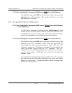
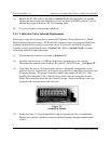
5.1.3 Electronic Circuit Board Replacement
Different models of the NetScanner
™
System Intelligent Pressure Scanner use different
combinations of the six (6) basic circuit boards described below. To the right of each section title
are the modules that contain the particular circuit board assembly. Also refer to the cross reference
in Table 5.1 for a summary of applicable components in each Intelligent Pressure Scanner.