


Pressure Systems, Inc. NetScanner™ System (9016, 9021, & 9022) User’s Manual
www.PressureSystems.com
3 - 10
need for external pressure generators. All 9016 models have built-in pneumatic inputs (CAL side
inputs) and calibration manifolds required for directing the generated pressures to the various
channels of the module(s) being calibrated. Models 9021 and 9022 require such pneumatic/
hydraulic plumbing be provided by the customer (if deemed necessary). Refer to Chapter 4 of this
manual for detailed background and procedures for periodic calibration of the Intelligent
Pressure Scanners. A summary of the commands used for calibration purposes is included below.
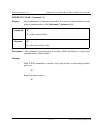
The Calculate and Set Offsets (‘h’) command is executed only when a suitable “minimum” (e.g.,
zero) pressure has been applied to all channels of the module. The new offset coefficients that
result from execution of this command are stored in the module’s volatile (or temporary)
engineering-unit conversion database. They are also returned to the host in the command’s
response.
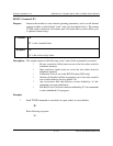
The Calculate and Set Gains (‘Z’) command should be executed only when “full-scale” (or other
suitable specified up-scale) pressure has been applied to the appropriate channels of a module. The
new gain coefficients that result from this command are stored in the module’s volatile (or
temporary) engineering-unit conversion database. They are also returned to the host in the
command’s response.
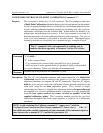
In modules using firmware version 2.24 or later, a Configure/Control Multi-Point Calibration
(‘C’) command is provided. This command (actually 4 sub-commands) is an improvement over
the single calibration commands (‘h’ and ‘Z’) described above. Though ‘C’ provides for the
adjustment of the same offset and gain correction coefficients already described above, it does so
with two or more applied pressure calibration points. The final linear fit (i.e., new offset and gain
correction coefficients) is a “least squares” correction fit between all the calibration points specified.
This ‘C’ command is particularly useful in calibrating differential transducers over their entire
negative-to-positive range.
Although the calculated offset and gain correction coefficients are kept in volatile memory
following execution of the calibration commands, they may be stored in non-volatile transducer
memory following the execution of the calibration commands (for use by all subsequent EU
conversions).
This is accomplished with the Set/Do Operating Options (‘w’) command (Index 08 and 09).
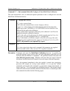
The above correction coefficients are maintained internally in IEEE floating-point format. The Read
Internal Coefficients (‘u’) command and the Download Internal Coefficients (‘v’) command can
return (or manually set) calibration coefficients to the host in decimal or hex dump formats in their
responses.