


Extron • System 4
xi
Switcher Series • User’s Manual
Chapter 4 • Connecting Multiple Switchers
System 4xi with SW4/6 ARMX Switchers
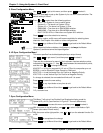
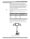
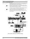
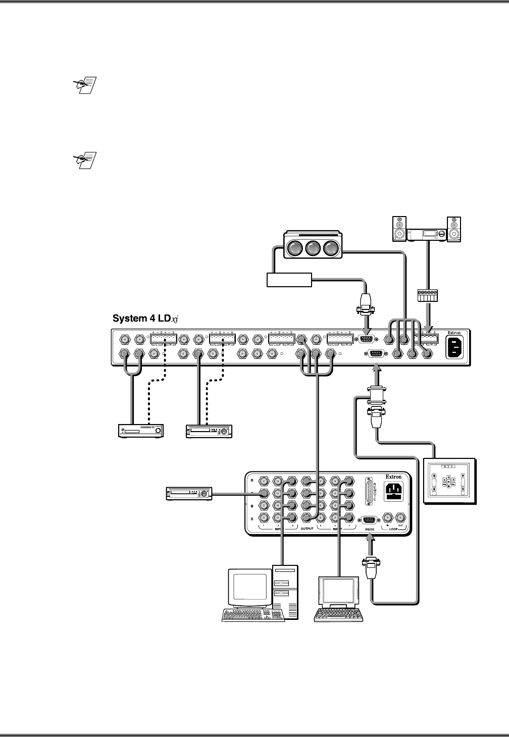
The picture in Figure 4-2 shows an SW6 ARMX as an example, although it would
also apply to an SW4 ARMX. Connect the video output of the ARMX switcher
(SW4 or SW6) to the last (4th) input of the System 4xi.
_______ Regardless of how the slave switcher input connectors are marked, they must
conform to the inputs of the System 4
xi
. They are: R/C, G/Y/Video, B, H/HV & V.
Note that composite video uses the G/Y connector.
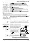
The System 4xi will control the ARMX switcher through the secondary RS-232
port, by way of a System 4xi Slave Adapter described on page 4-2.
_______ Jumper E2 inside the SW4/6 must be moved from “Normal” to “Slave Sys4”
position to allow it to act as a slave. (See SW4/6 documentation.)
After making all the cable connections, go to page 4-7 to configure the master/
slave as a system.
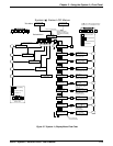
Figure 4-2. System 4
xi
Master with an SW6 ARMX Slave Switcher
SW 6 AR MX
Rear Panel
* Do not connect Pin #4
or Pin #8 (improper slave
operation will occur)
OUTPUT
PJ COMM
RS-232
M
A
N
U
A
L
AUDIO AUDIO AUDIO AUDIO AUDIO
H/HV
R/C G/Y BR/C G/Y B
V
INPUT 4
H/HV V
R/C G/Y B
INPUT 3
H/HV V
R/C G/Y B
INPUT 2
H/HV V
R/C G/Y B
INPUT 1
H/HV V
Projector Communication
Extension Cable
Projector
Comm Adapter
BNC Cable
System 4
Slave Adapter
(26-386-01)
Projector
2-Channel
Stereo Audio
VCR/VTR with Audio
Laserdisc Player
with S-video Outputs
and Stereo Audio
VCR
Control System
Laptop ComputerSVGA Compatible
Computer
4-3