


Extron • System 4
xi
Switcher Series • User’s Manual
Chapter 4 • Connecting Multiple Switchers
System 10 Plus
Rear Panel
Audio*
OUTPUT
PJ COMM
RS-232
AUDIO AUDIO AUDIO AUDIO AUDIO
H/HV
R/C G/Y BR/C G/Y B
V
INPUT 4
H/HV V
R/C G/Y B
INPUT 3
H/HV V
R/C G/Y B
INPUT 2
H/HV V
R/C G/Y B
INPUT 1
H/HV V
Projector Communication
Extension Cable
Projector
Comm Adapter
BNC Cable
System 4
Slave Adapter
(26-386-01)
Projector
2-Channel
Stereo Audio
Laserdisc Player
with S-video Outputs
and Stereo Audio
VCR
Control System
Laptop ComputerSVGA Compatible
Computer
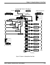
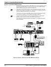
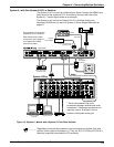
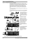
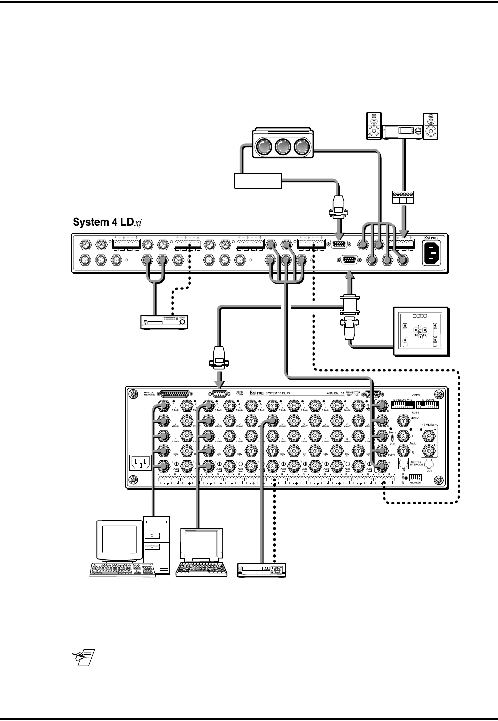
System 4xi with One System 8/10 PLUS Switcher
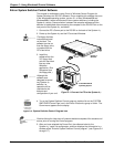
The System 8/10 PLUS must be configured as a Slave. Connect the RGBHV and
Audio output of the System 8/10 PLUS switcher to the last (4th) input of the
System 4xi. Use the figure below as an example.
The System 4xi will control the System 8/10 P
LUS Switcher through the
secondary RS-232 port, by way of a System 4xi Slave Adapter described on
page 4-2.
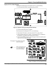
Go to page 4-6 to set up the
System 8/10 P
LUS switches.
After making all the cable
connections, go to page 4-7
to configure the master/
slave as a system.
*
Extron recommends that audio
connections between switchers be wired
unbalanced. If balanced connections are
required, insert a -6 dB pad in-line to
maintain 0 dB system audio gain.
Figure 4-3. System 4
xi
Master with a System 10 Plus Slave Switcher
_______ Regardless of how the slave switcher input connectors are marked, they must
conform to the inputs of the System 4
xi
. They are: R/C, G/Y/Video, B, H/HV & V.
Note that composite video uses the G/Y connector.
4-4