Extron • Matrix 3200/6400 Series • User’s Manual
Chapter 2 • Installing the Matrix 3200/6400 Wideband Video Switchers
9. System Video, Sync and Audio Cabling
Using work-sheets and/or printouts from the Matrix 6400 System Virtualization/
Control Program, install video and sync cables as required. Figure 2-2.B shows
the connectors for the optional MKP 1000 keypads.
Using the Sync Termination Switches
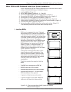
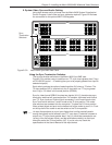
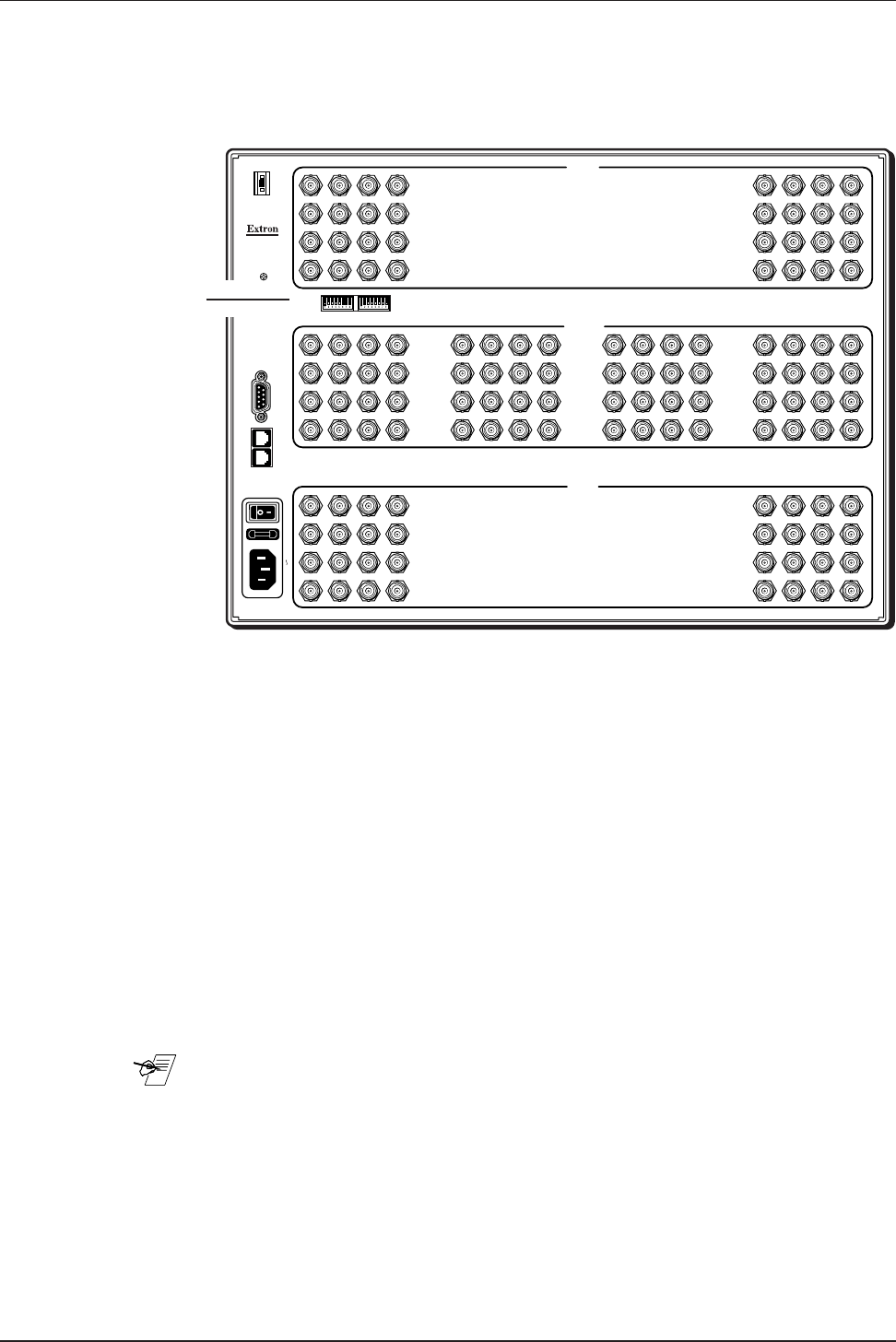
The sync termination switches on the Matrix 6400 Sync BME (see
Figure 2-5.A) provide a way to condition non-TTL sync levels greater than 5 Vp-p
on PHYSICAL inputs 1 - 16 enabling the sync to be properly passed from input to
selected output(s).
Each switch provides the option of selecting either 510 ohms or 75 ohms. The
75 ohms position (UP) is required only for an input with non-TTL sync greater
than 5 Vp-p, 510 ohms is the normal position (DOWN).
Sync for video format RGBHV involves two signals (H & V), therefore two sync
termination switches will require attention. For example, Horizontal and Vertical
non-TTL Sync inputs on Physical Input connectors 1 and 2 would require that
Sync Termination switches 1 and 2 be set to the 75 ohm position. The rocker
type switches are recessed into the rear panel. To select the 510 ohm position
use a pointed object and push on the bottom half of the rocker to push it in. Push
on the top half of the rocker to set the switch to the 75 ohm position.
____ An input that produces an out of sync display that is rolling vertically and/or
tearing horizontally could indicate a non-TTL sync input. If a device is known to
output non-TTL sync levels greater than 5 Vp-p, it should be connected to one
(or two) of the first sixteen inputs, and the termination switch(s) for that input
should be set to the 75 ohm position (UP). If you’re not sure, check the
specifications in the User’s Manual for the input device.
Figure 2-5.A Matrix 6400 Sync BME Rear Panel
AC POWER INPUT
FUSE: 250V 0.8A TT
IN
75 OHM
510 OHM
INPUTS 1 - 16
18916
BME
ADDRESS
ANAHEIM, CA
MADE IN USA
OUT
100-240V 0.5A MAX 50/60Hz
MKP COMM.BME COMM.
1
5
9
13
2
6
10
14
3
7
11
15
4
INPUTS
INPUTS
OUTPUTS
8
12
16
33
37
41
45
34
38
42
46
35
39
43
47
36
40
44
48
17
21
25
29
18
22
26
30
19
23
25
31
20
24
28
32
1
5
9
13
2
6
10
14
3
7
11
15
4
8
12
16
17
21
25
29
18
22
26
30
19
23
27
31
20
24
28
32
33
37
41
45
34
38
42
46
35
39
43
47
36
40
44
48
49
53
57
61
50
54
58
62
51
55
59
63
52
56
60
64
49
53
57
61
50
54
58
62
51
55
59
63
52
56
60
64
A
B
C
D
E
A
B
C
D
E
4
-
+
Sync
Termination
Switches
2-5


