


Extron • Matrix 3200/6400 Series • User’s Manual
Chapter 5 • Upgrades and Troubleshooting
Troubleshooting a Matrix 3200/6400 System Problem
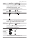
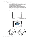
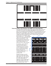
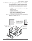
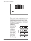
All Matrix 3200/6400 BME front panels include LEDs at the bottom of the panel
which are bracketed and labeled DIAGNOSTICS. These LEDs (Figure 5-6.A)
indicate the current status of the BME power supplies, the RS232/BME/MKP
1
Communications RX and TX lines, and the System Status. The following
descriptions include normal/failure/status conditions for each LED.
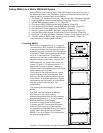
Power Supplies
Primary +V Green LED ON = Normal
OFF = Failure
Primary -V Green LED ON = Normal
OFF = Failure
Redundant +V Green LED ON = Normal
OFF = Failure (or Redundant not present)
Blinking = Redundant +V supplying full +V load
(indicates Primary +V power supply failure)
Redundant -V Green LED ON = Normal
OFF = Failure (or Redundant not present)
Blinking = Redundant -V supplying full +V load
(indicates Primary -V power supply failure)
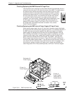
______ If a BME fails to power ON, check the BME external AC fuse (see Page 5-6).
If the Diagnostic LEDs indicate that a power supply has failed, check the power
supply fuse (see Page 5-6).
BME #0 must be powered ON at the same time or after other BMEs. Any BME
powered on after BME #0 will not be seen by the internal system software.
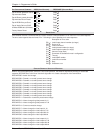
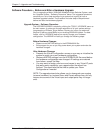
Communications
RS232 TX - Red LED ON/Blinking = BME is transmitting data to Host
RS232 RX - Green LED ON/Blinking = BME is receiving data from Host
BME TX - Red LED ON/Blinking = BME is transmitting data
BME RX - Green LED ON/Blinking = BME is receiving data
MKP TX - Red LED ON/Blinking = BME is transmitting to Remote keypad
MKP RX - Green LED ON/Blinking = BME is receiving from Remote keypad
______ 1. MKP TX/RX LEDs are not present on SYNC BMEs.
2. MKP LED conditions above apply only to BME #0.
3. RS-232 LED conditions above apply only to BME #0.
4. A communications failure between BME #0 and other BMEs could be caused
by one BME loading down the BME TX or RX line. To determine if that is the
case, run the RJ-45 BME COMM interconnecting cable to bypass each BME
one at a time.
Communication Failure Message
A communication failure between BME #0’s main controller and the FPC 1000 (if
present) may result in an error message display on the FPC 1000 LCD screen.
There is no indication of this error on the front panel and it will not occur on a
system that does not have an FPC 1000. The error message follows:
Communication Failure ##
Record the information following “Communication Failure” and call Extron
Technical Support.
System Status Amber LED ON = Normal
OFF = System failure
Blinking = Busy or possible minor problem
5-5