Extron • Matrix 3200/6400 Series • User’s Manual
Chapter 3 • Tutorial - Using the Matrix 3200/6400 System Virtualization/Control Software
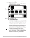
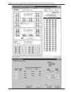
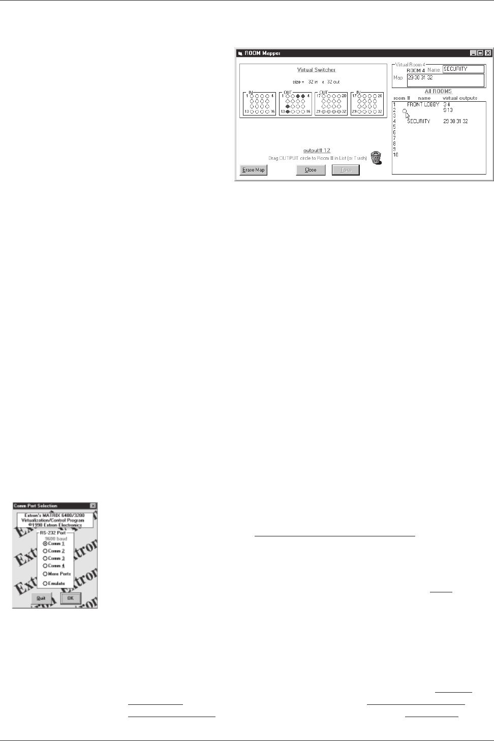
• From the menu on the Main screen, click SYSTEM-CONFIG to show the Virtual
Switch Virtual Map screen (Figure 3-4.A). From the Virtual Map screen menu,
click CONFIGURE|ROOM
CONFIGURE to show the
Room Mapper screen
(Figure 3-7.A).
Associate a Virtual
Output with a room
number by using the
mouse to drag the
output circle to the list
on the right side. You
can remove a Virtual
Output from a room by
dragging the circle to
the trash-can. You can add a name to the Room or edit it by typing in the text-
box. Click on the ‘OK’ button to save your changes or ‘Cancel’ to abandon your
changes. Press ‘Close’ to return to the Virtual Map screen.
• From the Virtual Map screen menu, click RETURN TO MAIN and note that a list-box
for the defined rooms should appear below the ‘Audio Mute’ button. The Room
mapping of the system is now complete and the map is stored in BME #0.
Unless the map gets destroyed or needs to be regenerated because of a system
hardware reconfiguration (size, type, or number of BMEs changes) or you wish
to change the room configuration, there is no requirement to use the Windows
Virtualization/Control software. You can, however, continue to use it to control
and program (set Ties, Presets, etc.) the system at any time.
How to REMOTE CONTROL PROGRAM the Matrix 3200/6400 System
Because the Matrix 3200/6400 Switchers store their settings in a nonvolatile
memory, programming applied to the unit from the Virtualization/Control Program
(or the FPC) is remembered in the unit. The Program only needs to talk to the
Matrix system long enough to create (program) the settings. You can, however,
leave a computer connected (dedicated) to the Matrix for real-time interactive
control and monitoring if you wish.
• To control or program the switcher system in real-time, establish an RS-232
connection between the PC and BME #0 of the Matrix 3200/6400 System. Start
the MTRX6400 program (under Windows) and click on the corresponding COMM
PORT number when asked. Click OK, or.....
If you wish to program a system without being connected to it at this time, click
on EMULATE. Follow steps in How to Off-Line (Emulate) Program the Matrix.
• The program will communicate with the Matrix 3200/6400 System to determine
its hardware configuration (type and size of each connected BME). It then reads
the system’s settings (Ties, Presets, Virtual Map, etc.) and draws a graphical
representation of the unit’s configuration and settings (Ties) on the Main screen.
It also reads the MTRX6400.INI file (saved from last session) to draw Icons for
each I/O (if any had been applied in previous programming sessions) to make
the graphical representation even more friendly.
NOTE: If this is a new system that has not been virtualized yet or one that has
had its map cleared by a System Reset, the graphical representation and all
information shown on the Virtual Map screen may be invalid at this time.
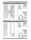
• Initially, the “Current configuration” from the Matrix is shown. Notice How the
Ties Appear as solid lines in various colors here and How the I/O Ports are
Grouped and Titled. Selecting a Preset (if any exist) from the Presets List at
3-7
FIGURE 3-7.A


