Extron • Matrix 3200/6400 Series • User’s Manual
Chapter 1 • Introduction to the Matrix 3200 & 6400 Wideband Video/Sync Switchers
Matrix 3200 & 6400 Wideband Video/Sync System Overview
A Matrix 3200/6400 system may consist of 1 - 6 BMEs (Basic Module
Enclosures). The user’s current and future video and audio switching
requirements will determine the size and configuration of the system. For
example, a 21 input by 21 output by 3 video signal (21x21x3) Matrix Wideband
Video Switcher system for video format RGB w/Sync on Green and no audio
would require one 6400 Wideband Video Switcher (a single BME). However, a
64x64x5 matrix switcher capable of switching video format RGBHV plus audio
would require three 6400 Wideband Video Switchers (3-BMEs), two 6400 Sync
Switchers (2-BMEs) plus an Audio module (1-BME).
The BME set to address #0 is referred to as BME #0 and is designated as the
Main Controller. The remaining BMEs (each with a unique BME address 1 - 5)
are controlled as one by interconnecting communication links. System options
include the FPC 1000 Front Panel Controller (1 per system to BME #0 only) and
MKP 1000 Remote Key Pads (up to 64 per system).
Virtual input and output assignment is a powerful feature of the Matrix 3200/
6400 Series. One or more physical input connectors may be assigned as any
Virtual Input number, the same is true of the output connectors. Virtual input and
output assignments are done through BME #0’s RS-232/RS-422 port with a PC
using Extron’s Matrix 3200/6400 System Virtualization/Control Software. This
will probably need to be done during initial system installation (before installing
video and audio cables) and would not normally need to be repeated unless the
system configuration changed. After the Virtual inputs and outputs have been
assigned (the system has been Virtualized) the video/sync/audio cables are
installed. Input/output selection (Ties and/or Presets) may be done through the
RS-232/RS-422 port with a PC Host or from a touch screen or any other user-
supplied controlling device, such as AMX, Crestron, etc., that is capable of
generating the proper commands, or, with an optional FPC 1000 Front Panel
Controller.
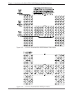
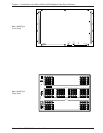
The work-sheet in Figure 1-4.A is an example of a Virtualized 21x21x3 Matrix
6400 Wideband Video Switcher. The physical BNC connector numbers are silk-
screened 1 - 64 on the rear panel. Virtual assignments are shown within the
circles, for example, physical input and output connectors 1 - 3 are labeled R01,
G01 and B01. R, G and B identify the color signals (Red, Green and Blue)
supported by the connectors. The two digits identify the Virtual input or output
assignment for that connector.
For the above example, physical Input connectors 1 - 3 are Virtual Input #1.
Physical Output connectors 1 - 3 are Virtual Output #1. If Virtual Input #1 is tied
(switched) to Virtual Output #1, the device connected to physical output
connectors 1 - 3 would receive the RGB signal supplied by the device connected
to physical input connectors 1 - 3. If Virtual Output #16 is also tied to Virtual
Input #1, the RGB signal from physical input connectors 1 - 3 will be available to
the device connected to physical output connectors 46 - 48.
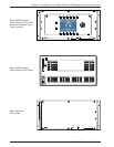
Adding a Matrix 6400 Sync BME to the example system above would upgrade it
to a 21x21x5 matrix switcher which would support video formats RGBHV, RGBS
and RGsB. The work-sheet in Figure 1-4.B shows a Matrix 6400 Sync module
virtualized for 21x21x5 matrix switching. Video and sync switching would occur
simultaneously due to the communication interconnection between the Matrix
6400 Sync and Matrix 6400 Wideband Video modules.
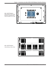
Blank Virtual Matrix work-sheets which may be copied and used to assist in
Virtualizing a system are provided in Appendix A .
A Matrix 3200/6400 System Virtualization/Control Software Tutorial with
instructions for Virtualizing a system is provided in Chapter 3 of this manual.
1-3


