Extron • Matrix 3200/6400 Series • User’s Manual
Chapter 5 • Upgrades and Troubleshooting
P/N 60-251-AA
P/N 60-251-AB
P/N 60-251-BC
P/N 60-251-BD
P/N 60-251-BA
P/N 60-251-BB
P/N 60-251-DC
P/N 60-251-DD
16
8
16
24
32
32
INPUTS
OUTPUTS
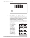
Determining Matrix 3200 Wideband Video BME Circuit Card Population
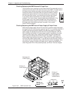
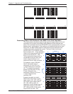
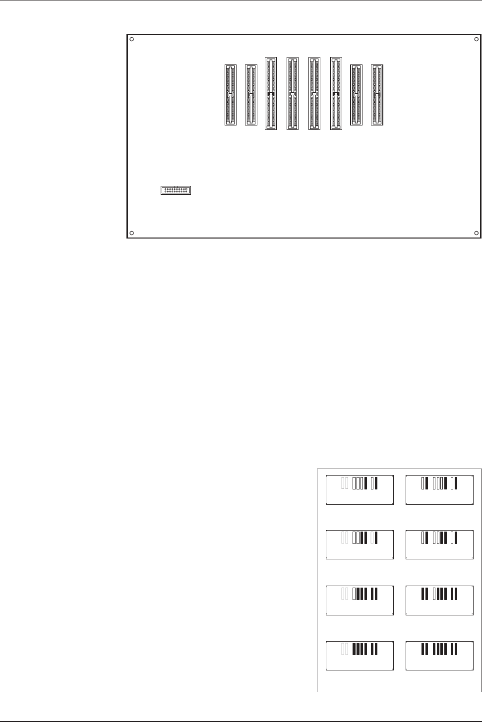
The drawing above shows the layout of the input and output video circuit card
connectors on the inside of the Matrix 3200 Wideband Switcher rear panel. The
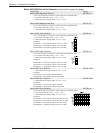
chart below shows the REQUIRED circuit card population for every possible
matrix configuration. If the cards are not installed as shown for each matrix size,
the Matrix 3200/6400 System Virtualization/Control Software will be unable to
accurately virtualize the system. The Input Video circuit cards
(PN# 70-082-01 or 70-066-01) plug into connectors JC1 - JC4, the Output Video
circuit cards (PN# 70-067-01) plug into connectors JD1 - JD4. The connectors
are keyed and it is not possible to plug an input card into an output connector or
an output card into an input connector.
For example, a matrix
32x8 will have 2-input
video cards in connectors
JC1 and JC4, and 1-output
video card in connector
JD1. To upgrade this
example system to a
matrix 32x16, plug a
1-output video card into
connector JD2.
A second example is a
matrix 16x16 which would
have 1-input video card in
JC1, and 2-output video
cards in JD1 and JD2. To
upgrade to a 32x16, plug
an input video card into
JC4. To upgrade from a
16x16 to a 32x24, plug
input video cards into JC2,
JC3 and JC4, and plug an
output video card into JD3.
5-10
1
2
19 J1
20
JC1JC2
JC3JC4
JD1
JD2JD3JD4


