


Extron • Matrix 3200/6400 Series • User’s Manual
Chapter 5 • Upgrades and Troubleshooting
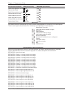
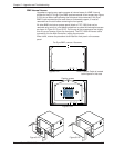
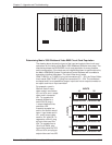
AC POWER INPUT
FUSE: 250V 0.8A TT
100-240V 0.5A MAX 50/60Hz
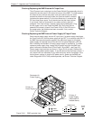
Checking/Replacing the BME External AC Input Fuse
The AC power input cord plugs into the Power-Switch/Fuse assembly which is
located on the rear panel in the lower left corner of the BME. To check/replace
the external fuse, remove the power-cord and insert the tip of a small
screwdriver blade into the fuse-holder slot (the fuse-holder is located
just below the power-switch). Pry the fuse-holder out, it contains the
AC input fuse plus a spare. If may be obvious that the fuse is blown,
if not, check it with an ohmmeter or any other continuity device if
available. If the fuse is blown, replace it with the provided spare. Plug
the AC power cord in and Power the BME ON. Verify that the unit
powered ON correctly (check Front Panel LEDs). If the LEDs are in
the proper state, the problem has been corrected. If not, contact
Extron Technical Support.
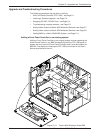
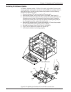
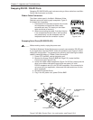
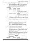
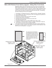
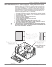
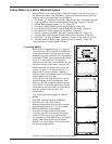
Checking/Replacing the BME Internal Power Supply AC Input Fuses
Each internal power supply has an AC input fuse. If a power supply fuse blows,
the Front Panel LED for that power supply will go OFF (it is normally solid ON). If
the BME has redundant power supplies, the redundant supply for the failed
power supply will assume the full load and its front panel diagnostic LED will
blink indicating that the Main (Primary) power supply is inoperative. To check/
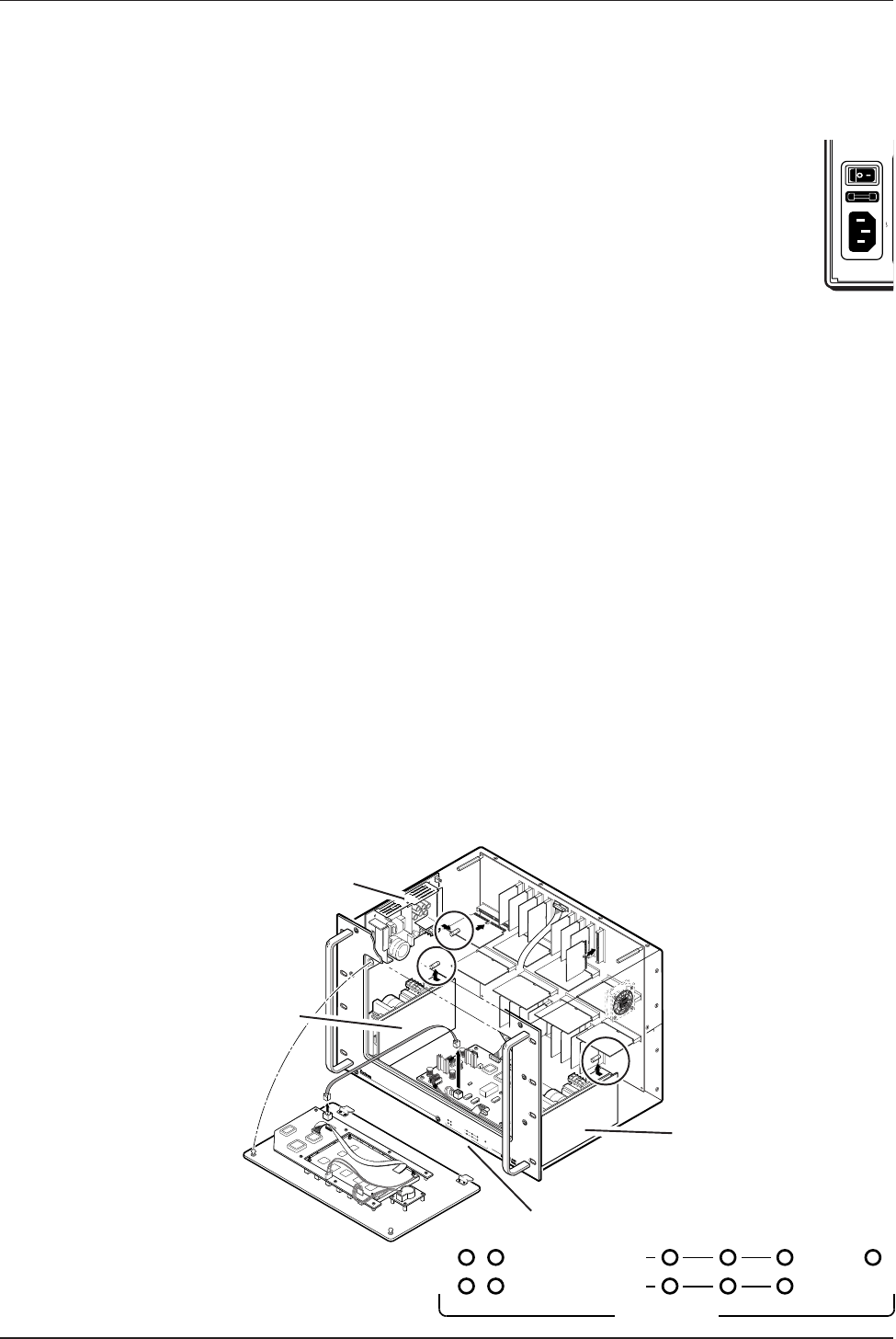
replace a power supply fuse, unplug the AC power cord from the BME rear
panel, remove the Access Panel (Front Panel if Sync BME - see Page 5-2).
Power supply fuse locations are shown in Figure 5-6.A (circled). Remove the
fuse from the problem power supply. If may be obvious that the fuse is blown, if
not, check it with an ohmmeter or any other continuity device if available. If the
fuse is blown, replace it, plug the AC power cord in, power up the BME and
check Diagnostic LEDs. If the problem persists, call Extron Technical Support.
5-6
POWER SUPPLIES COMMUNICATIONS
PRIMARY TX
RS232 BME MKP
SYSTE
M
STATU
S
REDUNDANT RX
DIAGNOSTICS
+
V
-
V
Redundant V+
Power Supply
Primary V+
Power Supply
1
2
19 J1
20
HIGH VOLTAGE
CAUTION
Fuse
Cable
Fuse
HIGH VOLTAGE
CAUTION
POWER SUPPLIES COMMUNICATIONS
PRIMARY TX
RS232 BMEREMOTE
SYSTEM
STATUS
REDUNDANT RX
DIAGNOSTICS
+
V
-
V
Fuse
Primary V-
Power Supply
(Redundant V-
located above)
Figure 5-6.A BME exploded view.