


Extron • Matrix 3200/6400 Series • User’s Manual
Chapter 5 • Upgrades and Troubleshooting
BME Internal Access
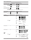
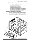
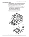
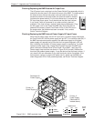
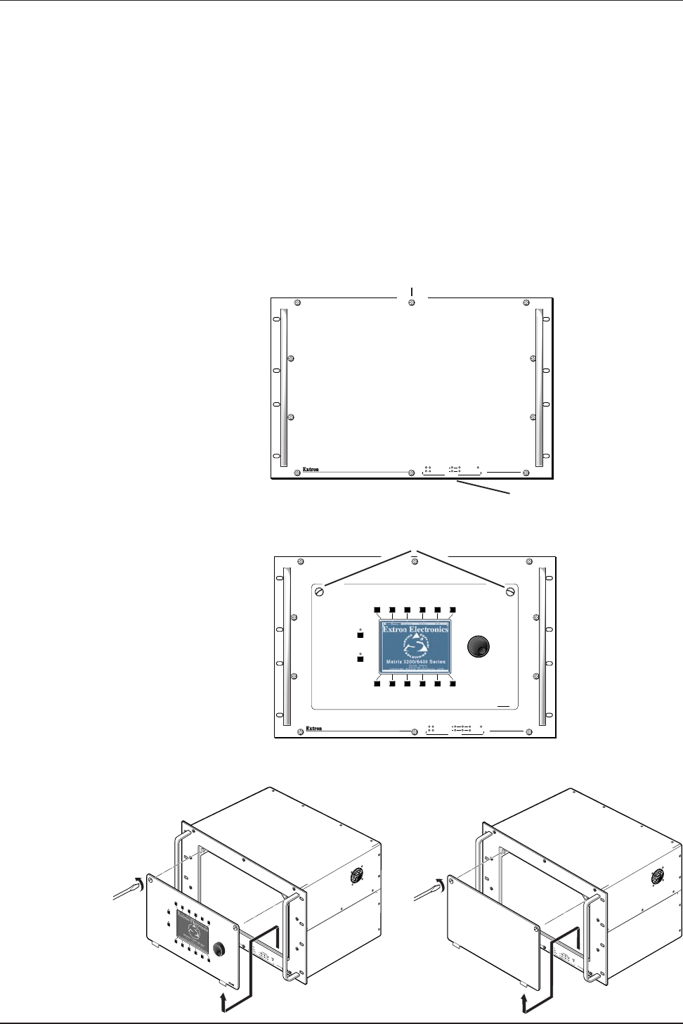
Upgrades or repairs may require access to internal areas of a BME. Internal
access for the 5U/7U high Sync BME requires removal of ten screws (see Figure
5-2.A) plus a ribbon cable allowing the front panel to be removed (if the Sync
BME is rack mounted and the case has no underneath support, it must be
removed from the rack before removing the front panel).
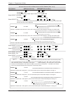
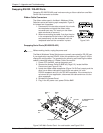
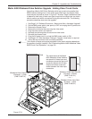
All other BMEs include an access panel (blank or FPC 1000) that can be
removed using a coin or a flat blade screwdriver to rotate the two captive screws
as shown in Figure 5-2.C and 5-2.D. Pull the top of the access panel out slightly
then lift up and remove it from the front panel. The FPC 1000 will have a cable
connecting it to the Main Controller, unplug the connector.
When done, reverse the procedure to reinstall the front panel or the access
panel.
Figure 5-2.B
Figure 5-2.D
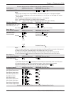
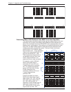
RGB
MUTE
AUDIO
MUTE
Figure 5-2.C
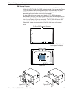
MATRIX 6400
SYNC
POWER SUPPLIES COMMUNICATIONS
PRIMARY TX
RS232 BME
SYSTEM
STATUS
REDUNDANT RX
DIAGNOSTICS
+
V
-
V
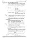
MATRIX 6400
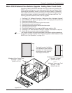
WIDEBAND
POWER SUPPLIES COMMUNICATIONS
PRIMARY
RGB
MUTE
AUDIO
MUTE
TX
RS232 BME
MKP
SYSTEM
STATUS
REDUNDANT RX
DIAGNOSTICS
+
V
-
V
FPC-1000
Captive screws
Figure 5-2.A
For Sync BME, remove 10 screws.
A Ribbon Cable is located
behind panel in this area
5-2